
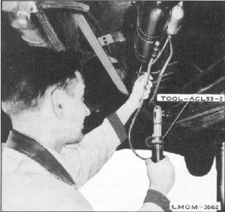
Fig. 17. Check for Leaks - (Step 3)
figure 17. NOTE: It is suggested that
some Freon be allowed to escape from a
Freon tank at some distance from the
vehicle. This Freon can then be detected
with the Leak Detector, Tool - ACL53-
2, and the exact color of the flame
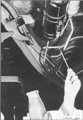
4. If Freon is detected, it may be pin-
pointed exactly by using Liquid Leak
Detector. The liquid solution, when mixed
according to instructions and "painted on" a
leak, will form bubbles around the exact
location. See figure 18.
5. Repair all leaks and turn off the flame in
Leak Detector, Tool - ACL53-2.
REMOVAL OF COMPRESSOR
ASSEMBLY
1. Drain coolant from radiator and cylinder
block.
2. Install Pressure Test Gauge Manifold,
Tool - ACL53-3, with both gauge
valves turned in the full clockwise
position so that the high
Fig. 18. Check for Leaks - (Step 4)
pressure gauge hose is connected to the
high pressure valve service port and the
low pressure gauge hose is connected to
the low pressure valve service port.
3. Turn low pressure valve, located on right
front fender apron, and high pressure valve,
located on the condenser, 1-1/2 turns in the
clock-wise direction, using Tool-ACL53-5.
Both gauges will read neutral sys-tem
pressure (Approximately 50 - 7 5 P.S.I. at
an outside air temperature of approximately
70
0
- 750). See figure 11.
4. If both gauges read neutral system
pressure, pump system down by following
"Pump Down Procedure".