
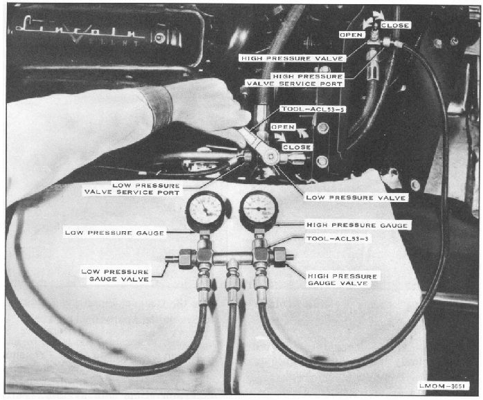
Fig. 11. Install Pressure Test Gauge Manifold
4
Both pressure gauges of the Pres-sure
Test Gauge Manifold, Tool - ACL53-3,
will read neutral sys-tem pressure
(approximately 50 - 75 P.S.I. at an
outside air temperature of approximately
70
0
- 75
0
.) See figure 11.
If the gauge readings are below normal,
or there is no pressure indicated, attach
center hose of the Pressure Test Gauge
Manifold, Tool - ACL53-3, to the Freon
tank and turn low pressure gauge valve
counterclockwise until open. Open
5
6.
Freon tank valve until both gauges read
same pressure. See figure 12.
Check all connections and replaced
parts for leaks.
Turn low pressure valve of the Pressure
Test Gauge Manifold, Tool - ACL53-3
clockwise until seated, shut off Freon
tank valve, disconnect Freon tank from
manifold center hose, cap tank fitting.
7. Turn low pressure gauge valve of the
Pressure Test Gauge Manifold,