| 29 of 35 |  |
the inverted air horn on a level
surface so the
float can be gauged (consult Holley
catalog sheets
for the proper float gage, part number
and speci
fications.) Reset the gage on the
float horizontal
surface of the air horn with the
gage just touching
the float, but not lying across
the soldered seam.
Make adjustments by bending the
rounded tab,
which contacts the head of the fuel
inlet needle
(see "A" in Figure 38).
When the properly closed
float reading has been made, lift
the float to the
full open position. Any accurate
depth gage may
then be used to measure the distance
from the
float to the air horn. Adjustments
on the float
lever to limit the travel may be
made only by
bending the small tab which contacts
the side of
the fuel inlet seat (see "B"
in Figure 38).
E.
REASSEMBLY - AIR HORN ASSEMBLY
MODEL 2110-G
1. Slide choke shaft in position
in the
air horn. Insert the choke plate
in slot of the choke
shaft. (Correct shaft position noted
during dis
assembly.) Install choke plate screws
snugly but
not tight. Rotate the choke shaft.
If no binding
occurs and little or no light appears
between the
plates and the walls of the bore
when plates are
closed, tighten the choke plate
screws securely.
Using a suitable staking tool, stake
the choke plate
screws.
2. Slide the choke wire bracket
as
sembly on the choke shaft, place
the throttle spring
lever in position and install the
screw and lock
washer. Place the choke lever clamp
on the choke
shaft in the correct position and
install the screw
and nut.
3. Install fuel inlet valve and
seat as
sembly, using Kent-Moore Tool No.
10-183.
Tighten securely to prevent leakage
past the new
gasket. Check to make certain the
fuel inlet needle
is inserted with the point up towards
seating sur
face.
only by bending the rounded tab
which contacts
the fuel needle. (See "A"
in Figure 38). Afterthe
proper closed setting has been
made, lift thefloat
to"°the full open position.
Any accurate depth gage
may be used
to measure the distance from the
float to the air horn. Adjustments
on the float
lever may be made to limit the
travel of the float
only by bending the small tab which
contacts the
side of the fuel inlet valve seat.
(See "B" in Fig
ure 38.)
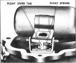
Fiqure 39. Correct Position of
Float Spring
5. Install the fuel inlet connection
and
the governor line connection fitting.
F.
REASSEMBLY - THREE MAJOR
SUBASSEMBLIES MODELS 2110-EE,
2110-EEC AND 2110-FF
1. Place a new throttle body gasket
on
the throttle body and align the
holes. Set the main
body on the throttle body, taking
care that the holes
in the gasket remain in alignment.
Position the
choke bracket or control rod bracket
- if included.
Insert the three throttle body
to main body screws
and lockwashers.
NOT
4. Install float spring and float
spring
retainer. Holding the float and
lever assembly
in position, slide the float shaft
into position.
Place the inverted air horn on
a level surface so
the float can be gaged. (Consult
current Holley
Catalog sheets for proper float
gage, part number,
and specifications.) Reset the
gage on the flat
horizontal surface of the air horn
with the gage
just touching the float. Do not
gage the float on
the soldered seam. Adjustments
should be made
Tighten the three screws alternately,
a little
at a time, to compress the gasket
evenly.
2. Install the pump link. The three
holes in the throttle lever permit
adjustment of
the accelerating pump discharge.
The outer hole
provides a maximum pump discharge
for extreme
cold weather operation, and the
inner hole pro
vides a minimum pump discharge
for hot weather.
However, for most driving conditions,
the middle
hole should be used.
Install the two retainers.
-27-