| 28 of 35 |  |
1. Reassemble the dashpot assembly.
Install the dashpot on bracket, with
one lockwasher
on either side of the bracket, secure
the nut.
(AUTOMATIC TRANSMISSIONS.)
2.
Install the connection fitting and
new
gasket.
3. Slide the choke shaft assembly
into
the air horn, also install the choke
shaft spring,
if included.
4. Install the choke plate. Invert
the
air horn, and with the lug on the
choke shaft as
sembly pointed upward, insert the
choke plate in
the slot on the choke shaft. Install
the choke plate
screws and run them down until they
are snug but
not tight. Close the choke plate
and hold the air
horn up to the light. Little or
no light should show
between the choke plate and the
walls of the bore.
If the choke plate is properly installed
and there
is no binding when it is operated,
then tighten the
choke plate screws. Using any suitable
staking
tool, stake the choke plate screws.
NOTE: The next 2 steps pertain only
to Models
2110-EE and 2110-FF.
5. Insert the choke plunger spring
and
choke plunger.
6. Set the choke lever and swivel
as
sembly in place and install the
screw and lock
washer. The tab on the choke shaft
lever should
be positioned in the "V"
shaped notch of the choke
lever and swivel assembly.
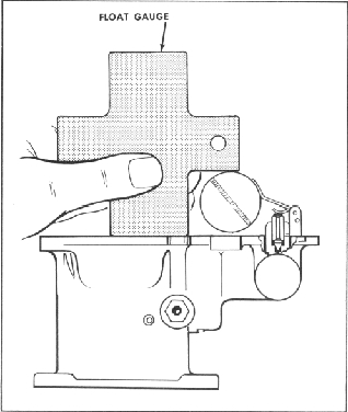
Figure 37.
Gauging Float
11. ,Rotate the thermostat housing
until
the index mark on the rim of the
cover is aligned
with large center indicator on the
choke housing.
Install the three thermostat screws
and clamps.
12. Using Kent-Moore Tool No. 10-183,
install the fuel inlet valve and
seat assembly and
new gasket.
NOTE: The next 5 steps pertain only
to Models
2110-EEC.
7. Place the new choke housing
gasket
in position and install the choke
housing with the
two screws and lockwashers.
8.
Insert the thermostat lever, link
and
piston in its chamber with the
end of the lever fit
ting on to the choke shaft. Position
the choke shaft
spacer, lockwasher and nut, tighten
firmly.
9. Place the choke housing plate
and
thermostat housing gasket in position.
10.
Place the thermostat housing in
posi
tion, with the looped end of the
thermostat spring
on the thermostat lever.
13. Holding the float and lever
assembly
in position, slide the float shaft
in position. Place
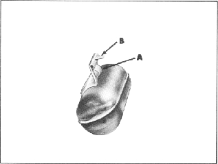
Figure 38.
Float Adjustments