| 27 of 35 |  |
9. Place bearing retainer spring
and
seal retainer over the throttle shaft
in the throttle
body. Set new governor housing gasket
inposition
on the throttle body, aligning the
holes in the
gasket and throttle body. Install
leather seal (tips
toward housing) in the governor
housing and place
governor in position. Align the
holes in governor
housing, governor housing gasket
and the throttle
body, and insert the three governor
to throttle body
screws and lockwashers, and tighten.
Check to see
if throttle shaft moves freely and
does not bind.
10. Slide the governor lever over
the
throttle shaft and insert end of
the diaphragm rod
through governor lever. Install
cotter pin in the
diaphragm rod, bending both ends
of the cotter pin
back toward the head. Install the
governor lever
nut and lockwasher.
11. With the throttle plates open,
loop
one end of the governor spring to
the governor
lever spring pin, and snap the other
loop of the
spring to the stationary pin in
the governor housing.
Do not stretch the spring more than
is necessary.
12.
Install the governor cover with
anew
gasket. Insert the four governor
cover screws
and lockwashers. Install safety
wire and seal.
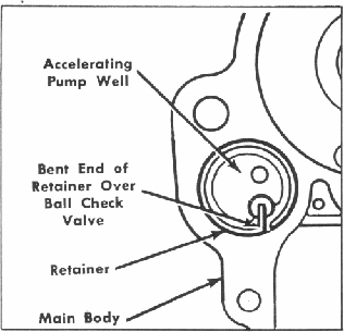
Figure 36. Replacing Ball Check
Valve
6. Insert the pump discharge valve
in
position and install the pump discharge
nozzle and
new gasket.
7. Install the idle tube assemblies
into
the nozzle bars.
13.
Install the vacuum connection fitting.
C.
REASSEMBLY - MAIN BODY
ASSEMBLY ALL 2110-SERIES
8. Using four new gaskets, install
the
two nozzle bars.
9. Place the two nozzle bar clamps
in
position and install the four screws.
1. Install a new pump operating
shaft
felt seal and secure with the washer.
2. Install a new pump operating
rod
lubricator ring and secure with
the washer.
3. Install the accelerating pump
inlet
ball check valve. Place a small
brass rod on the
ball and tap lightly with a fiber
mallet to insure
proper seating of the ball. Care
must be taken to
prevent damage to the ball or seat.
Check to see
if ball is still movable. Install
the check valve
retainer in the accelerating pump
well of the main
body. The bent-in portion of the
retainer holds
the ball in place.
4. Install the economizer valve
as
10. Place the throttle kicker spring
and
lever in position and install the
screw and lock
washer. (Model 2110-EE and 2110-FF)
11. Reassemble the accelerating
pump
assembly. First place the pump
spring on the
pump piston assembly, then install
the spring
washer on the pump piston assembly.
Compress
the spring and slide the pump operating
rod into
the slot on the piston assembly
until the notches
in the washer engage the cutout
in the arm. Place
the pump return spring on the operating
rod. Slide
the accelerating pump assembly
into place in the
main body housing. Take care that
the piston cup
does not catch on the lip of the
pump chamber.
sembly and new gasket, using Kent-Moore
Tool
12. Insert the pump rod stud in
position.
No. 10-175.
5. Using Kent-Moore Tool No. 10-174
D. REASSEMBLY - AIR HORN ASSEMBLY
install the two main jets. Install
the two main jet
MODELS 2110-EE, 2110-EEC AND
passage plugs and new gaskets.
2110-FF