| 26 of 35 |  |
3. Install the dashpot adjusting
screw
and nut (If included).
4. Install the throttle stop screw
and
spring.
5. Install the throttle stop screw
and
spring. While holding the throttle
plates almost
closed, turn the screw in until
its tip contacts the
tab at the end of throttle operating
shaft lever.
5. Slide the fast idle cam on the
stud
and install the fast idle cam retainer.
- Model
2110-EEC.
6. Slide the throttle lever assembly
in
place and insert throttle lever
clamp screw and
nut.
6. Install the spark valve assembly
with a new gasket. (If included).
7.
Install the two idle adjusting springs
and needles.
B.
REASSEMBLY - THROTTLE BODY
ASSEMBLY MODEL 2110-G
1. Install bearing on governor side
of
the throttle body. Slide the throttle
shaft and bear
ing assembly into the throttle body,
and install
bearing retainer. (Correct position
of shaft noted
during disassembly.)
2. Referring to lines and figures
scribed
on the throttle plates during disassembly,
install
the throttle plates. Insert the
four throttle plate
screws snugly, but do not tighten.
Close the throt
tle plates and hold the throttle
body up to the light.
Little or no light should show between
throttle
plates and the walls of the throttle
bores. If the
throttle plates are properly aligned,
there will be
no binding when throttle lever is
operated. Using
an approved staking tool, tighten
the throttle plate
screws. If it is necessary to use
an impact type
of staking tool, be sure to back
up the heads of the
throttle plate screws to prevent
bending the throttle
shaft when staking.
3. Install the throttle operating
shaft
assembly in throttle operating housing.
Position
the two screws and lockwashers in
the housing.
Place the new gasket over the ends
of the screws
and with the throttle plates held
in the closed
position, set the assembly in place
on throttle
body, making sure the throttle
operating shaft
lever assembly is in the open position.
If the as
sembly is properly installed, the
throttle plates
will be closed when the throttle
operating lever
is up.
4. Install the dashpot adjusting
screw
and nut in the throttle lever clamp.
(If included).
7.
Install the two idle adjusting
needles,
with the original springs. Turn
the needles by
hand until they seat in the idle
discharge holes.
Then back them off one complete
turn. Do not
force the needle against its seat,
as this will groove
the tip of the needle, make it
impossible to correctly
adjust the idle mixture.
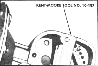
8. Place the diaphragm and rod
as
sembly in the governor housing.
Take care that
all the holes in the diaphragm
are aligned with
the threaded holes in the rim of
the governor
housing. The bent end of the rod
should point out.
Place the diaphragm cover in position,
making
sure the vacuum passage holes in
the governor
housing, diaphragm and diaphragm
cover are all
correctly aligned. Insert the diaphragm
cover
screws and lockwashers, spacing
evenly the three
screws drilled for the safety wire.
Turnthescrews
in until the flanges almost meet
but do not tighten.
Place the governor diaphragm gage
(Kent-Moore
Tool No. 10-187) on the governor
housing as shown
in the illustration. Hook the end
of the diaphragm
rod into the slot provided in the
gage, and then
tighten the eight diaphragm cover
screws securely
before removing the gage. This
procedure will
stretch the diaphragm sufficiently
to insure full
travel of the diaphragm for proper
governor oper
ation. Install a new safety wire
and seal.
Figure 35. Installing Governor
Diaphragm Cover