
(5) Check the choke plate for binding by moving
the choke lever through the extent of its travel. If it
moves freely, tighten the choke plate screws while
holding the choke plate in the fully closed position.
Stake the screws (on carburetor models having choke
plate screws without lockwashers) using any
approved staking tool. If an impact type staking tool,
such as a punch, is used, each screw head should be
braced with a solid object to prevent bending the
choke shaft. Take care not to nick or mar the venturi
or choke plate with the staking tool.
(6) Install the choke bracket screw and lock-
washer.
freely in their chambers, then install the pump
discharge valve weight and the two retainers.
NOTE
It is extremely important that these parts are
correctly installed or carburetor performance will be
adversely affected.
(10) Using Snap-On Tool No. TMC-36, install the
new main jet in the main well and economizer body.
(11) Place the new main well and economizer
body spacer gasket in position over the accelerating
pump diaphragm.
(7) Place the pump operating lever on the stud in
the main body and secure it by fitting the new pump
operating lever retainer in the groove at the end of
the shaft.
(12) Install the pump return spring, seating the larger end
of the spring in the metal disk of the accelerating pump
piston.
(8) Place the pump spring on the rod of the new
pump diaphragm and rod assembly. Position the pump
rod sleeve on the pump diaphragm rod with the small
hole in the sleeve aligned with the center of the flat
cutaway portion of the rod. Press the sleeve on the
rod, compressing the pump spring, and drop the new
pump rod sleeve retainer ball into the small hole in the
pump rod sleeve. Insert the assembly into position in
the main body.
(9)
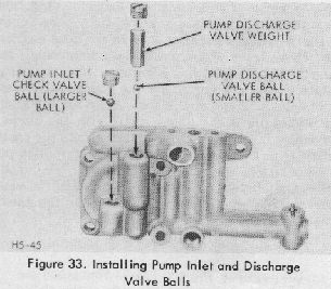
Install the pump inlet check valve ball and
the pump discharge valve ball in the main well and
economizer body. (The pump inlet check valve ball is
the larger of the two balls.) The new steel balls are to
be seated by placing a thin brass rod on the top of
each ball and tapping the rod very lightly three or four
times with a fiber mallet, Shake the casting to insure
that the balls move
Figure 34. Installing Main Well and Economizer
Body
(13) Align all holes in the main well and economizer
spacer gasket with the corresponding holes in the
accelerating pump diaphragm and the main body.
Insert the five main well and economizer body screws
and lockwashers in the main well and economizer
body with the two long screws placed in the center
top and bottom holes. Set the power valve situated at
the extreme right end of the main well and
economizer body into its position in the main body,
then press the main well and economizer body into
place against the accelerating pump diaphragm using
the following procedure. Grasp the main
.
body in the
left hand, holding the thumb over the protruding end
of the pump rod sleeve and the fingers over the main
well and economizer body. Apply pressure with
thumb and fingers to compress the pump spring and
pump return spring. This pressure must be applied
evenly to prevent the tension of the pump return
spring from disturbing the alignment of the holes in
the diaphragm, spacer gasket, and the main body.
After the main well and economizer body
