7. Remove power piston spring(s) from power piston cavity.
FIGURE 32
8. FLOAT ASSEMBLY REMOVAL:
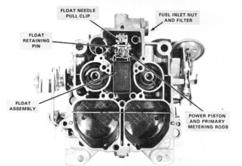
A. DIAPHRAGM TYPE - (Figure 32)
1. Remove float assembly by pulling upward on hinge pin until pin can be removed from float hanger by sliding toward pump well. After pin is removed, slide float assembly toward front of bowl to disengage needle pull clip from float arm. Do not distort float needle pull clip.
2. Using needle-nosed pliers, remove pull clip from float needle.
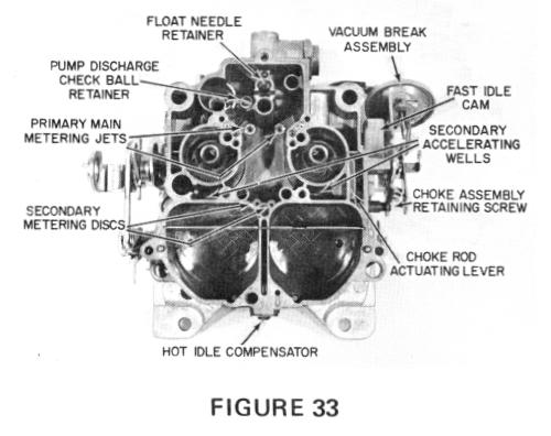
3. Remove two screws from float needle dia
phragm retainer; then remove retainer and float
needle assembly from bowl (Figure 33). CAUTION: Needle seat is factory staked and tested. Do not attempt to remove or restake. If damaged, replace float bowl assembly.
FIGURE 34
B. STANDARD TYPE NEEDLE AND SEAT -
(Figure 34)
1. Remove float assembly by pulling upward on hinge pin. Float needle and hinge pin can now be removed from float assembly.
2. Remove float needle seat and gasket from float bowl using tool BT-3006.
NOTE: Float needle and seat are factory matched and tested and should be replaced as a set.
9. Remove primary main metering jets. No attempt should be made to remove secondary metering orifice plates. Normal cleaning is all that is necessary.
10. Using a screwdriver, remove pump discharge check ball retainer, then steel check ball.
11. The baffle plate in secondary bores need not be removed for cleaning purposes. It can be removed for replacement by lifting straight upward, out of slots in side of bores.
12. CHOKE DISASSEMBLY:
A. 4MV MODELS - (Figure 35)
1. Remove vacuum break hose from main vacuum break assembly and, if used, from rear (or auxiliary) vacuum break assembly, and remove hose(s) from connection on float bowl.
2. Remove retaining screw from choke vacuum break bracket assembly and remove assembly from float bowl. If not removed previously, vacuum break rod can now be removed from