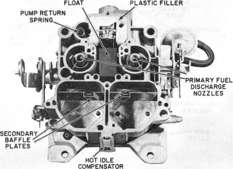
FIGURE 29
FLOAT BOWL DISASSEMBLY - (Figure 29)
1. Remove pump plunger from pump well.
2. Remove air horn gasket from dowels on secondary side
of bowl, then remove gasket from around power piston
and primary metering rod and lift gasket from bowl.
3. Remove pump return spring from pump well. 4. Remove plastic filler block over float valve.
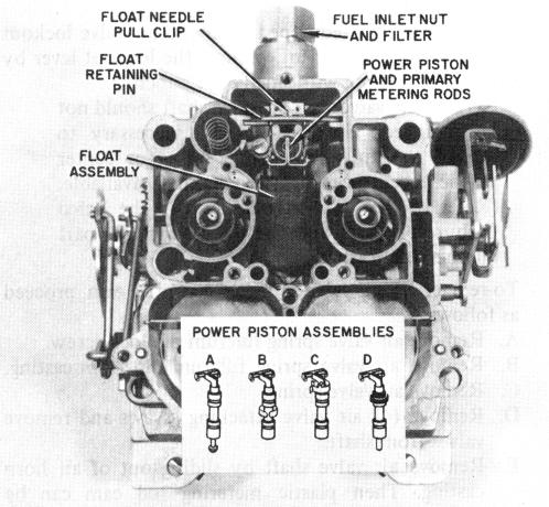
5. Remove power piston and primary metering rods as an
assembly. There are four different type power piston
retainers used. (See Figure 30.)
CAUTION: Do not remove power piston by using pliers on metering rod holder.
A. The first design has a "button head" pin extension pressed into the base of the power piston. This type power piston is held in place by the "button head" which protrudes through a hole in the throttle body gasket. The power piston can be removed by using needle-nosed pliers to pull straight up on metering rod hanger directly over power piston.
B. The second type power piston retainer is a flat brass spring clip which fits around the power piston, at the center. This type power piston assembly is removed in the same manner as above.
C. The third type power piston retainer is a spring clip which fits over and around the top of the power piston cavity. Two fingers at the top of clip hold the piston down in cavity. This type power piston can be removed by pushing upward on clip retainer to disengage from casting.
D. The fourth power piston retainer is a plastic retainer which is part of the power piston assembly. The plastic retainer fits in a recess at the top of the power piston cavity. The power piston with the plastic retainer can be removed by pushing downward against spring tension and allowing the piston to snap back against the retainer until it "pops" out of casting. This procedure may have to be repeated several times to free power piston retainer.
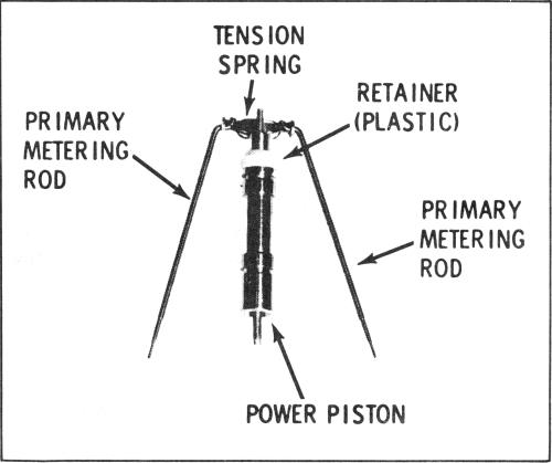
6. Remove primary metering rods from power piston by
disconnecting tension spring loops from top of each
rod. Then rotate each metering rod to remove from
hanger.
CAUTION:: Use care when disassembling rods
to prevent distortion of tension spring and/or
metering rods. Note carefully position of ten
sion spring for later reassembly (See Figure 31).
POWER PISTON AND METERING RODS (Fig. 31)
FIGURE 30
FIGURE 31