the main vacuum break plunger by rotating rod out of plunger stem.
3. Remove secondary lockout lever or idle speedup lever (where used) from projection on bowl casting.
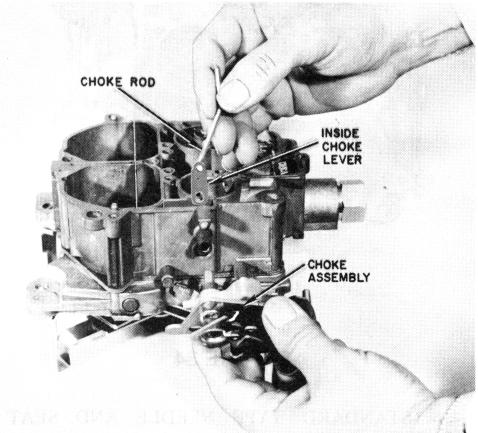
CHOKE AND FAST IDLE MECHANISM - R&R (Figure 35)
FIGURE 35
4. Remove the fast idle cam from bushing on choke vacuum break bracket assembly.
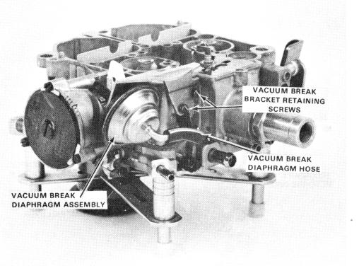
NOTE: If further disassembly of the choke vacuum break assembly is necessary, the vacuum break assembly can be removed as follows:
(a) (Early Models) Remove clip on connecting link at vacuum break lever. Then, remove link from lever and vacuum break diaphragm plunger.
(b) (All Models) Spread the retaining ears on bracket for removing either the primary vacuum break diaphragm assembly or the secondary vacuum break assembly. The secondary vacuum break assembly has a rod connecting the plunger to the intermediate choke shaft lever. This can also be removed by rotating the vacuum break diaphragm assembly and sliding rod out of plunger stem and the other end out of vacuum break lever.
CAUTION: Do not place vacuum break assemblies in carburetor cleaner.
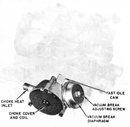
FIGURE 36
B. EARLY 4MC MODELS - (Figure 36)
1. Remove (3) choke cover screws and retainers. Then remove cover and coil assembly and inside baffle plate from choke housing.
2. Remove attaching screw from inside choke housing. Then remove choke housing assembly from float bowl. Remove vacuum passage gasket between choke housing and float bowl.
3. Remove fast idle cam from choke housing.
CAUTION: Do not place vacuum break diaphragm assembly in carburetor cleaner.
4MC BOWL ASSEMBLY (Fig. 37)
FIGURE 37