
4. ACCELERATING PUMP SYSTEM
As the throttle opening is suddenly
increased
for acceleration, the air flow through
the carbu
retor responds almost immediately.
Since fuel,
however, is heavier than air, there
is a brief
interval before fuel flow responds
to the increase
in the throttle opening. During that
short period,
since the desired balance of fuel
and air cannot
be maintained by the other fuel metering
systems,
the accelerating pump becomes functional,
sup
plying fuel until the other metering
systems can
provide the proper mixture.
The accelerating pump, connected to
the
throttle lever by the pump link, is
actuated by
throttle movement. When the throttle
is moved
toward the closed position, the pump
piston is
raised by the linkage, charging the
accelerating
pump well with fuel. This upward movement
of
the piston draws fuel from the float
chamber
through the pump inlet and into the
pump well.
The pump inlet check valve opens to
permit fuel
to enter the pump well and closes
to prevent a
reverse flow of fuel when the pump
is in operation.
As the throttle is opened, the pump
rod is drawn
downward by the pump link. When the
pump rod
moves downward, the horizontal arm
in its upper
end slides down in the slot in the
piston stem,
compressing the pump spring.
This over-riding
feature of the pump discharge valve
provides a
ACCELERATING PUMP SYSTEM
prolonged, even discharge of fuel,
for smooth ac
celeration. The pressure of the compressed
spring moves the pump piston downward.
This
forces the fuel, in the bottom of
the pump well,
out through the pump discharge passage,
raising
the pump discharge needle valve. The
fuel flows
around the needle and is metered through
the
calibrated pump discharge nozzle into
the air
stream entering the venturi. The pump
discharge
valve prevents the syphoning of fuel
f rom the pump
well at high speeds, also prevents
air from enter
ing the pump chamber on the loading
stroke.
A larger or smaller accelerating pump
dis
charge, to compensate for climatic
conditions,
can be obtained by varying the position
of the pump
link pin in the holes provided in
the throttle lever.
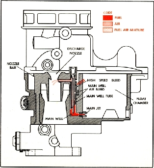
5. MAIN METERING SYSTEM
As the engine is running, the intake
stroke
of each piston draws the air through
the carbu
retor venturi and booster venturi.
The air, passing
through the reduced area of the venturi,
creates
a low pressure commonly called a
vacuum. The
strength of this low pressure is
determined pri
marily by the velocity of the air
flowing through
the venturi. This, in turn, is regulated
by the
speed and power output of the engine.
The dif
ference, between the pressure in
the venturi and
the normal air pressure in the float
chamber,
MAIN METERING SYSTEM
