| 7 of 35 |  |

If the engine should
approach a stall at an
time during the warm-up period, manifold
vacuum
will become weak. The tension of the
thermosta
spring then overcomes the reduced force
actin
on the vacuum piston and the choke
plate will b
moved toward the closed position,
providing
richer mixture to allow the engine
to "catch" an
run smoothly again.
NOTE
Inasmuch as this dual carburetor has
two
identically functioning barrels, only
one side
will be considered in the following
explana
tions of the four basic fuel metering
systems.
AUTOMATIC CHOKE
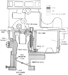
3. IDLE SYSTEM
At idle and low speeds, the engine
does not
draw sufficient air through the venturi
to create
a vacuum strong enough to operate
the main
metering system. Because of the almost
closed
throttle plates which greatly restrict
air flow into
the manifold at idle and low speeds,
manifold vacu
um is high. This high manifold vacuum
provides
a pressure differential which operates
the idle
system.
At idle, the greatly reduced pressure
area
below the throttle plates causes the
fuel to flow
from the float chamber through the
idle system.
From the float chamber, the fuel proceeds
through
the main jet into the main well, and
then into the
idle tube. The fuel moves upward through
the idle
tubes and flows through holes in the
side of the
head of the tube into the horizontal
channel of the
nozzle bar. The calibrated restriction,
in the
lower tip of the idle tube, meters
the flow of fuel
into the idle system. Air is added
to the raw fuel
by means of the idle air bleed in
the horizontal
channel. The booster venturi is circular
and the
fuel can flow through the channels
on either side.
After leaving the nozzle bar, the
fuel-air mixture
continues down the idle passage in
the throttle
body past the idle transfer holes
which act as ad
ditional air bleeds when the throttle
plate is in
the curb idle position. The fuel then
passes through
the idle discharge hole into the strong
manifold
vacuum below the throttle plates.
The idle dis
charge hole is equipped with an idle
adjusting
needle to control the mixture delivered
at idle.
During off idle operation, the throttle
plate
is moved slightly past the idle transfer
holes,
causing them to cease functioning
as air bleeds,
and begin to discharge fuel because
of being ex
posed to manifold vacuum. As the
throttle plate
is opened still wider and the engine
speed in
creases, the air flow through the
carburetor is
also increased. This creates a pressure
dif
ferential in the venturi strong enough
to bring
the main metering system into operation.
The
flow from the idle system tapers
off as the main
metering system begins discharging
fuel. The
two systems are engineered to provide
a smooth
even transition from idle to cruising
speeds.
IDLE SYSTEM