| 5 of 35 |  |
3. MAJOR SUBASSEMBLIES
Carburetor Model 2110 Series is composed
of three major subassemblies: the air
horn as
sembly, the main body assembly, and
the throttle
body assembly. The air horn contains
the choke
mechanism, the balance tube for venting
the float
chamber to the carburetor air inlet,
and the float
assembly which actuates the fuel inlet
valve. The
die cast main body contains the float
chamber, the
accelerating pump, the diaphragm type
power
valve, and the removable fuel metering
parts, such
as the main jets, idle tubes, and
booster venturi
nozzle bars. The cast iron throttle
body contains
the throttle plates and the idle speed
and mixture
adjusting screws. Carburetors used
with auto
matic transmission engines have a
bracket
fastened under the air horn screws
on which to
mount the dashpot assembly. Model
2110-EE and
2110-FF Carburetors have a choke bracket
or a
throttle control bracket. Carburetor
Model
2110-EEC has an automatic choke which
is an
integral part of the carburetor. Model
2110-G
has a built in Centri-Vac governor.
OPERATION
To meet the requirements of modern
auto
motive engines, the carburetor must
supply the
proper fuel-air mixture during all
phases of
operation. The Holley Carburetor Model
2110
Series, to provide the correct mixture,
is equipped
with four basic metering systems.
They are the
idle system, the accelerating pump
system, the
main metering system, and the power
enrichment
system. These four systems are individually
calibrated to deliver an economical
mixture for
normal cruising conditions; a richer
mixture when
high power output is desired, and
a still richer
mixture for smooth idle and low speed
perform
ance, also the accelerating pump provides
fuel
for instant acceleration.
In addition, there is a fuel inlet
system, which
provides the four basic metering systems
with a
constant supply of fuel, and also
a choke which
provides a means of temporarily enriching
the
mixture to aid in starting and running
a cold engine.
When the engine is running, differences
in air
pressure within the carburetor provide
the proper
discharge of fuel for the various
engine speed and
load conditions, as explained in
the following
paragraphs. In the explanation of
the basic fuel
metering systems, the air in the
carburetor float
chamber will be considered as being
at normal
atmospheric pressure. It may actually
be at a
pressure very slightly less than
atmospheric, due
to the restriction of the air flow
through the air
cleaner. However, to simplify the
explanation of
the function of the fuel metering
systems, this
factor will be disregarded and the
pressure will
be considered as being atmospheric.
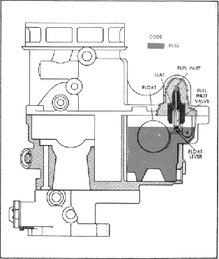
1.
FUEL INLET SYSTEM
All of the fuel, for the four basic
metering
systems, enters the carburetor through
the fuel
inlet valve. This valve is frequently
referred to
as the fuel inlet needle and seat
assembly. The
amount of fuel entering the carburetor
is deter
mined by the amount of space between
the tip of
the needle and its seat. Movement
of the needle
in relation to the seat is controlled
by the float
and lever assembly.
Movement of the float and
lever assembly is in turn regulated
by fluctuations
in the fuel level. Even a slight
drop in the fuel
level causes the lowering of the
float to open the
needle valve, allowing more fuel
to enter the float
chamber.
When the fuel in the float chamber
reaches a specified level, the needle
valve is
forced upward by action of the float
thus restricting
FUEL INLET SYSTEM