| 31 of 35 |  |
5.
First set one of the two idle adjusting
needles for the highest steady manifold
vacuum
reading. If a vacuum gage is not
available get the
smoothest running maximum idle speed
by turning
the idle adjusting needle in until
the rpm begins to
drop off, then backing the needle
off over the "high
spot" until the rpm again drops
off. Set the idle
adjusting needle halfway between
these two points
for a satisfactory idle mixture
setting. Then re
peat the procedure with the other
needle.
Final
fine adjustment may vary slightly
from this set
ting but should not exceed 1/2 turn
difference
between the screws. Should these
adjustments
show an increase in idle rpm, reset
the throttle
stop screw to obtain the specified
idle rpm and
adjust the idle adjusting needles
again.
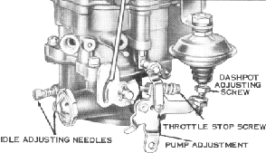
B. ADJUSTING THE DASHPOT
The dashpot, on carburetors for
engines
equipped with automatic transmission,
is to be
adjusted after the idle speed and
mixture settings
have been completed. Close the throttle
lever
slowly to the idle position, with
the choke fully
open. Set the dashpot adjusting
screw to conform
to the clearance specified in the
Holley Carburetor
Company Parts Catalog.
C. ADJUSTING THE AUTOMATIC CHOKE
1. The automatic choke is accurately
set at the factory to give the best
possible all
weather operation. To return the
choke to the
original setting, line up the index
mark on the
rim of the thermostat cover with
the specified
indicator on the choke housing.
2.
If for some reason a richer or leaner
mixture during the warm-up period
is desired, it
can be obtained by rotating the
thermostat cover.
Never set the index mark on the
cover more than
two graduations off the large center
indicator on
the housing.
D. ADJUSTING THE GOVERNOR
1. Connect a tachometer to the engine.
Start the engine and allow it to
warm up thoroughly
Race the engine for a brief interval
at wide open
throttle and note the engine speed
registered by
the tachometer. If an adjustment
is required,
stop the engine and remove the
adjusting hole plug
from the governor valve housing.
With the ignition
switch off, crank the engine, either
by hand or
with the starter, until the governor
valve adjusting
screw at the end of the governor
valve body ap
pears at the opening. Insert a
screwdriver though
the hole and turn the adjusting
screw clockwise to
increase speed or counterclockwise
to decrease
speed. One full turn of the adjusting
screw will
result in a change in top speed
of about 150 rpm.
Repeat the adjustment procedure
until the speed
is set to specifications. Install
the adjusting hole
plug and tighten securely. Attach
new locking
wire and seal to the adjusting
hole plug and the
adjacent fin.
Figure 40. Carburetor Adjustments
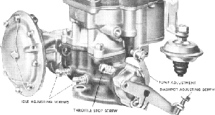
Figure 41 . Carburetor Adjustments
SERVICE HINTS
Carburetor service should be performed
only
with the use of proper equipment.
Approved equip
ment includes float setting gages,
together with
other special carburetor tools.
In addition, ap
proved specification sheets must
be utilized. Refer
to the Holley Carburetor Catalog
sheet for the
carburetor being overhauled to
find the proper
engine and carburetor specifications.
1. INSPECTING THE VEHICLE