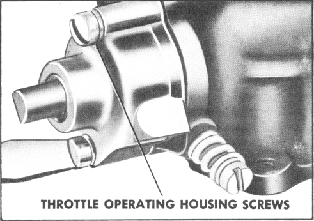


Figure 32. Removing Throttle Operating
Housing Screws
12.
Slide the throttle operating shaft
out
of the housing.
Remove the throttle stop screw
and spring.
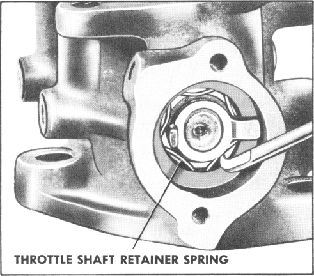
13. Using Kent-Moore Tool No. 10-188,
lift the wire throttle shaft retainer
spring out of
the slot in the throttle body.
Figure 33. Removing Throttle Shaft
Retainer
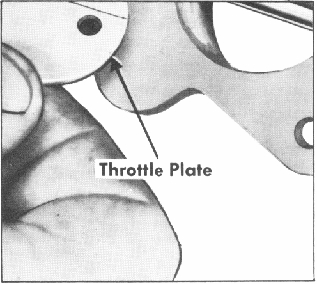
14. Lightly scribe both throttle
plates
along the throttle shaft and mark
each throttle
plate and its corresponding bore
with a number
or letter to insure proper replacement.
15. Remove the four throttle plate
screws, and slide the throttle plates
out of the
throttle shaft. Remove the throttle
shaft and
bearing assembly from the throttle
body. (Note
position of shaft for correct reassembly.)
Re
move the remaining bearing from
governor side
of the throttle body.
Figure 34. Removing Throttle Plates
5. CLEANING AND INSPECTION
A. CLEANING
1. Soak all castings and metal parts,
except the dashpot assembly and
nozzle bars, in
a cleaning solution until all foreign
deposits are
loosened. If a commercial cleaning
solvent is not
available, lacquer thinner or denatured
alcohol
may be used. Place the parts to
be cleaned in a
metal basket suspended in the solution
and agitate.
Avoid lowering the basket into the
sediment which
collects in the bottom of the container.
After the
parts have soaked sufficiently,
they are to be
rinsed in hot water to remove all
traces of the
cleaning solution. Scrub away all
remaining for
eign matter with a stiff bristle
brush while rinsing
the parts and castings. Only inlet
end of the noz
zle bars should be immersed in the
cleaning
solvent. DO NOT place the circular
booster
venturi in the solution.
2. Parts and castings should be
thor
oughly dried with compressed air.
Compressed
air should also be directed through
all passages
in the castings and through the
jets and nozzle
bars.
CAUTION
Carburetor jets and passages should
never
be cleaned with a wire, a drill,
or similar
abrasive objects. This method of
cleaning
may distort the jets and passages
and greatly
