| 14 of 35 |  |
3. While holding the throttle kicker
assembly back (Models 2110-EE and
2110-FF)
separate the air horn assembly from
the main
body assembly. Remove and discard
the carbu
retor body gasket.
4. Remove the two pump link retainers
and lift out the pump link assembly.
5. Remove the three throttle body
to
main body screws and lockwashers,
also the
control rod bracket or the choke
bracket. (Models
2110-EE and 2110-FF)
6. Separate the main body assembly
from the throttle body assembly
and discard the
throttle body gasket.
C.
DISASSEMBLY - THREE MAJOR SUB
ASSEMBLIES (MODEL 2110-G)
The following list contains all
parts to
be removed in separating the three
major sub
assemblies. During disassembly discard
all
gaskets, also parts which have replacements
in
the Master Repair Kits.
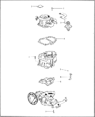
Figure 3.
Disassembly - Major Subassemblies
Model 2110-G
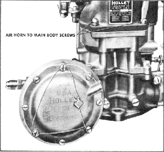
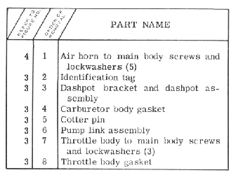
1. Remove the five air horn to main
body screws and lockwashers and
identification
tag.
Figure 4. Removing Air Horn Screws
2. Remove dashpot bracket and dashpot
assembly - if included.
3. Separate the air horn from main
body and discard the gasket.
4. Remove pump cotter pin and pump
link assembly.
5. Remove the three throttle body
to
main body screws and lockwashers.
6.
Separate the main body from
throttle
body and discard the gasket.