| 36 of 40 |  |
plates are properly installed, tighten
the throttle
plate screws and stake them.
be installed before installing the
choke shaft. See
step 12 following.
3. Replace the idle speed screw and
spring.
Turn the idle speed screw in approximately
14
complete turns.
4. Install a new throttle operating
shaft gasket
and, with the throttle plates held
in the closed
position, place the throttle operating
shaft into
place in the throttle body. The
accelerating pump
lever of the throttle operating
shaft should extend
toward the fuel inlet side of the
throttle body and
should be held down in the wide-open
throttle po
sition. When this assembly is properly
installed,
it should hold the throttle plates
closed when the
accelerating pump lever is up, but
should permit
the plates to move freely when the
lever is down.
11. Referring to the numbers and
lines scribed
on the choke plates during disassembly,
install the
choke plates, choke plate screws,
and lockwashers.
Carefully check to make sure the
choke plates work
freely and do not rub on the nozzle
tube extensions.
12. On carburetors having the choke
lever
separate from the choke shaft, install
the choke
bracket and choke lever and tighten
the choke
lever clamp screw.
5. Place the throttle operating
shaft housing
and hand throttle bracket in position
and install
the two throttle operating shaft
housing screws and
lockwashers.
6. Install the throttle lever. Carefully
line
up the hole in the throttle lever
with the hole in the
throttle operating shaft and drive
the throttle lever
pin in place. Tighten the throttle
lever clamp
screw.
7. Press the throttle shaft bearing
on the
governor side of the carburetor
into position.
8. Install the new idle adjusting
needles with
the original springs. With the fingers,
turn the
idle adjusting needles in until
they seat in the idle
discharge hole, then back them out
one full turn.
Be careful not to force either needle
against its
seat, as this will groove the tip
of the needle,
making it impossible to correctly
adjust the idle
mixture.
9. Place the new distributor check
valve ball
in its passage and install the
check valve retainer.
On the carburetors which also require
a check
valve spring, install the ball,
spring, and retainer,
in that order.
10. Install the choke shaft and
drum-like
nozzle tube extensions. Be sure
the narrow end
of the egg-shaped hole in each
nozzle tube extension
faces toward the idle adjusting
needle side of the
throttle body. On carburetors which
have the choke
lever riveted to the shaft, the
choke bracket must
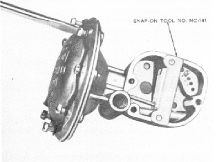
FIGURE 53. PROPER DIAPHRAGM STRETCHING
PROCEDURE
13. Place the new diaphragm and
rod as
sembly in the governor housing,
being sure that
all holes in the diaphragm are
aligned with the
threaded holes in the rim of the
governor housing.
The bent end of the rod should
point out. Place
the diaphragm cover in position,
being sure the
vacuum passage holes in the governor
housing,
diaphragm, and diaphragm cover
are all correctly
aligned. Insert the eight diaphragm
cover screws
and lockwashers, spacing evenly
the three screws
drilled for lock wiring. Turn the
screws in until
the flanges nearly meet but do
not tighten the
screws. Pull the end of the diaphragm
rod back
firmly to a point directly above
the threaded hole
for the governor cover screw at
the bottom of the