| 33 of 40 |  |

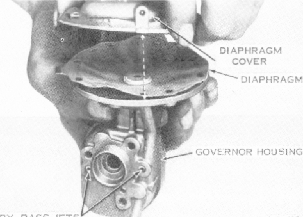
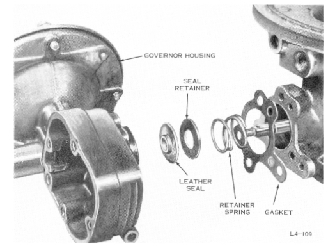
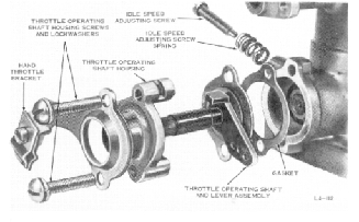
FIGURE 46. REMOVING GOVERNOR SEAL,
SEAL
12. Remove the governor housing gasket,
leather seal, seal retainer, and
seal retainer
spring. Discard the gasket and the
leather seal.
.4-
13. Remove and discard the diaphragm
cover
lead seal and wire. Remove the eight
diaphragm
cover screws and lockwashers.
14. Remove the diaphragm cover and
dia
phragm and rod assembly. Discard
the diaphragm
and rod assembly.
NOTE
Do not remove the two governor by-pass
jets "A" and "B".
They are to be removed,
cleaned and replaced one at a time
during
cleaning to avoid improper reassembly.
16. Remove the four throttle plate
screws
and the two throttle plates. Discard
throttle plate
screws. See figure 33.
NOTE
Before removing the throttle plate
screws,
the spread-out tip of each screw
due to
previous staking should be removed
to
prevent damagingthe threads inthe
throt
tle shaft. The tip of each screw
can be
removed by careful filing. Do not
damage
the throttle shaft or throttle plates
with
the file.
FIGURE 48.
REMOVING THROTTLE LEVER PIN
17. Using a flat tip punch or a
piece of 1/16
inch diameter drill rod, lightly
tap the throttle
lever pin out of the throttle lever.
18. Loosen the throttle lever clamp
screw
and remove the throttle lever.
19. Remove the two throttle operating
shaft
housing screws and lockwashers.
FIGURE 49. REMOVING THROTTLE OPERATING
SHAFT ASSEMBLY
15. Lightly scribe both throttle
plates along
the throttle shaft and lightly mark
the plates and
their corresponding bores with numbers
or figures
to insure proper reassembly. See
figure 32.
20. Remove and separate the hand
throttle
bracket, the throttle operating
shaft housing, the
throttle operating shaft and lever
assembly and the
throttle operating shaft gasket.
Discard the gasket.