| 31 of 40 |  |
Many of the steps in disassembling
the gov
ernor equipped throttle body are
similar
to those in the disassembly of the
pas
senger car carburetor throttle body.
In
the following steps, reference is
made to
the previous illustrations, where
appli
c abl e.
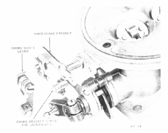
FIGURE 39. REMOVING CHOKE SHAFT
LEVER AND
BRACKET
NOTE
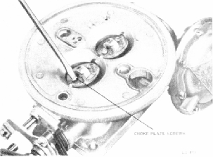
FIGURE 40. REMOVING CHOKE PLATE
SCREWS
5. With a screw driver, pry the
pump oper
ating rod seal and washer out of
throttle body.
Discard the seal and washer. See
figure 31.
NOTE
Current governor-equipped carburetors
have a pump operating rod seal which
is po
sitioned on the top surface of the
throttle
body and is held in place by a spring
and
washer around the pump operating
rod.
These parts will have been removed
earli
er in the disassembly procedure.
6. Remove the two idle adjusting
needles and
springs. Discard the idle needle..
See figure 25.
1.
Loosen the clamp screw and remove
the
choke shaft lever. Remove the screw
and lock
washer holding the hand choke bracket
to the
throttle body, and remove the bracket.
NOTE
Current governor-equipped carburetors
have a pump operating rod seal which
is po
Do not attempt to remove the choke
shaft
lever on these carburetors.
2. Very lightly scribe the choke
plates along
the choke shaft and lightly mark
them and their
corresponding bores with numbers
or letters to
insure proper reassembly. See figure
27.
3. Remove the four choke plate screws
and
the two choke plates.
FIGURE 41. REMOVING DISTRIBUTOR
CHECK
VALVE BALL AND RETAINER
7. Remove the distributor check
valve retainer
and check valve ball. If check valve
ball is nylon,
dis
NOTE
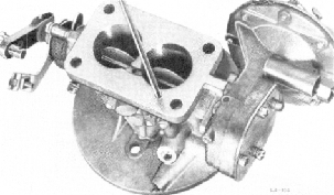
4. Carefully pull the choke shaft
out of the
throttle body and remove the nozzle
tube extensions.
See figure 30.
Some governor- equipped carburetors
also
have a spring in the distributor
vacuum
passage which must be removed.