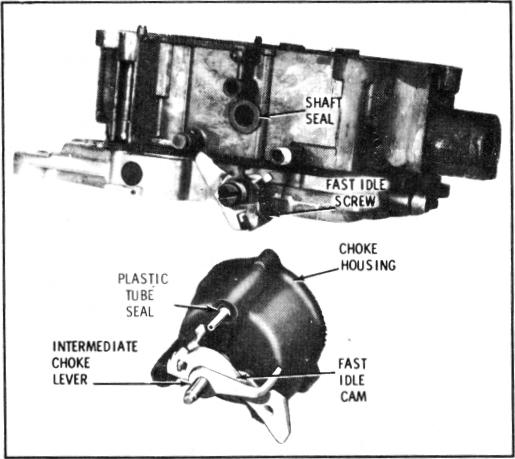
CHOKE HOUSING SEALING (Fig. 43)
FIGURE 43
ASSEMBLY OF CHOKE TO BOWL-LATE 4MC - (Figure 43)
L Install new cup seal into plastic insert on side of float bowl for intermediate choke shaft. Lip on cup seal faces outward.
2. Install fast idle cam on the intermediate choke shaft (steps on fast idle cam face downward) (Figure 43).
3. Install new rubber cup seal inside choke housing. Lips on seal should face towards carburetor bowl.
4. Carefully install fast idle cam and intermediate choke shaft assembly through seal in choke housing; then install thermostatic coil lever onto flats on intermediate choke shaft. Inside thermostatic choke coil lever is properly aligned when both inside and outside levers face towards fuel inlet. Install inside lever retaining screw into end of intermediate choke shaft. Tighten securely.
5. Install lower choke rod lever into cavity in float bowl. Install plastic tube seal into cavity on choke housing before assembling choke housing to bowl. Install choke housing to bowl sliding intermediate choke shaft into lower choke lever (Figure 35).
NOTE: Tool BT-6911 can be used to hold the lower choke lever in correct position while installing the choke housing (Figure 35).
6. Install choke housing retaining screw and washer and
tighten securely.
NOTE: The intermediate choke shaft lever and fast idle cam are in correct relation when the tang on lever is beneath the fast idle cam. Do not install choke cover and coil assembly until
inside coil lever is adjusted. (See Adjustment Procedures Bulletin 9D-5A of the Delco Carburetor Parts and Service Manual 9X).
COMPLETION OF FLOAT BOWL ASSEMBLY-ALL
MODELS - (Figure 34)
1. Install baffle in secondary side of float bowl with
notches toward top of bowl. Make sure baffle is seated
and top is flush with casting surface.
2. Install pump discharge check ball and retainer in
passage next to pump well. Tighten retainer securely. 3. Install primary main metering jets. Tighten securely.
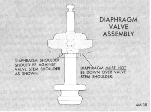
DIAPHRAGM TYPE NEEDLE INSTALLATION -(Refer to Figures 32 and 33)
4. Install float needle and diaphragm assembly, making
sure diaphragm is properly seated (Figure 44).
FIGURE 44
5. Install diaphragm retainer and two screws. Tighten securely.
6. Install float needle pull clip on float needle stem using needle nosed pliers. Pull clip is properly positioned with open end towards front of bowl.
7. Install float by sliding float lever into loop in pull clip. With lever in clip, hold float assembly at toe and install float hinge pin from pump well side. Be careful not to bend needle pull clip.
NOTE: If desired, certain Quadrajet models may be converted from the diaphragm type needle and seat to the standard or conventional float needle and seat by installing a service modification kit. (Refer to 9C Parts Section of the Delco 9X Manual for specific applications and part number.)
INSTALLATION OF STANDARD FLOAT NEEDLE AND SEAT -- (Refer to Figures 32 and 34, page 23.)
8. Install float needle seat and gasket. Tighten securely.