MODELS 4M-4MC-4MV PAGE 28
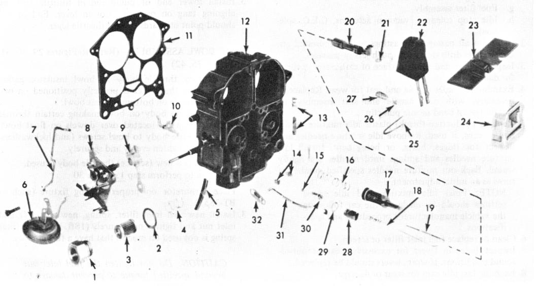
TYPICAL 4MV FLOAT BOWL EXPLODED VIEW (Fig. 42)
FIGURE 42
|
1. |
Fuel Inlet Nut |
9. |
Fast Idle Cam |
15. |
Pump Discharge Ball |
24. |
Float Bowl Insert |
|
2. |
Gasket |
10. |
Secondary Throttle |
16. |
Pump Return Spring |
25. |
Float Hinge Pin |
|
3. |
Fuel Filter |
Lockout |
17. |
Accelerator Pump |
26. |
Float Needle Pull Clip |
|
|
4. |
Fuel Filter Spring |
11. |
Throttle Body to Bowl |
18. |
Power Piston Spring |
27. |
Float Needle |
|
5. |
Vacuum Break Hose |
Gasket |
19. |
Primary Metering Rods |
28. |
Float Needle Seat |
|
|
6. |
Vacuum Diaphragm |
12. |
Float Bowl Assembly |
20. |
Power Piston |
29. |
Needle Seat Gasket |
|
7. |
Air Valve Dashpot Rod |
13. |
Idle Speed Screw |
21. |
Metering Rod Retainer |
30. |
Discharge Ball Retainer |
|
8. |
Choke Control Bracket |
14. |
Primary Jets |
22. |
Float |
31. |
Choke Rod |
|
23. |
Secondary Air Baffle |
32. |
Choke Lever |
ASSEMBLY OF CHOKE TO BOWL-4MV - (Figure 42)
8. Connect choke rod (plain end) to choke rod actuating lever - then - holding choke rod with grooved end pointing inward - position choke rod actuating lever in well of float bowl and install choke assembly, engaging shaft with hole in choke actuating lever. Install retaining screw and tighten securely. Remove choke rod from lever for installation later.
NOTE: Tool BT-6911 can be used to hold the choke lever while performing assembly of choke to bowl.
9. Install vacuum break hose(s) or rubber tee to tube connection on bowl and vacuum break assembly. If two
vacuum break diaphragm units are used, the shorter vacuum hose goes to the main or front vacuum break diaphragm unit.
ASSEMBLY OF CHOKE TO BOWL-EARLY 4MC - (Figure 36)
10. Install choke housing using step 8. Make sure small gasket is installed on vacuum passage between choke housing and float bowl. Install retaining screw and tighten securely..
NOTE: Choke inside baffle, cover and coil can be installed later after inside choke adjustments are made.