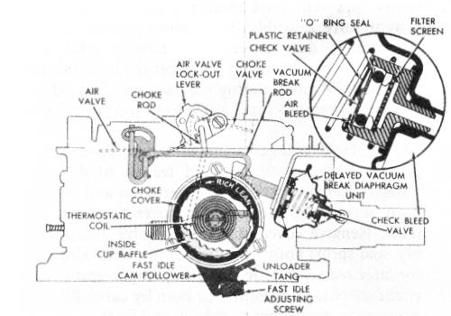
CHOKE SYSTEM - 4MC (LATE) (Fig. 24)
FIGURE 24
Later 4MC Quadrajet carburetors (Figure 24) use a delayed vacuum break system. An internal bleed check valve in the vacuum break diaphragm unit delays the diaphragm action a few seconds before it becomes seated. This allows the engine manifold to be wetted and engine friction to decrease enough so that when the vacuum break point is reached, the engine will run without loading or stalling.
When the choke valve moves to the vacuum break position, the fast idle cam follower lever on the end of the primary throttle shaft will drop from the highest step on the fast idle cam to the next lower step (second step) when the throttle is opened. This gives the engine sufficient fast idle speed and correct fuel mixture for running until the engine begins to warm up and heat the thermostatic coil in the choke housing. Engine vacuum pulls heat from the manifold heat stove into the choke housing and gradually relaxes choke coil tension. This allows the choke valve to continue opening through carburetor inlet air pressure pushing on the offset choke valve. Choke valve opening continues until the thermostatic coil is completely relaxed, at which point the choke valve is wide open and the engine is thoroughly warmed up.
During the last few degrees of choke valve opening, a tang on the choke lever contacts the secondary air valve lockout lever and rotates the lever counterclockwise so that the tang over the air valve will move completely away from the valve, allowing the air valves to open and operate.
The choke system on all 4MC models is designed to partially open the choke valve, should the engine become flooded or loaded. To unload the engine, the accelerator pedal must be depressed so that the throttle valves are held wide open. A tang on the lever on the choke side of the primary throttle shaft contacts the fast idle cam and through the .intermediate choke shaft forces the choke valve slightly open. This allows extra air to enter the carburetor bores and pass on into the engine manifold and cylinders to lean out the fuel mixture so that the engine will start.
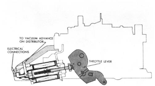
COMBINATION EMISSION CONTROL (C.E.C.) VALVE (Fig. 25)
FIGURE 25
On some Quadrajet applications, a carburetor mounted Combination Emission Control (C.E.C.) valve is added to help reduce exhaust emissions (Figure 25). A vacuum tube in the float bowl is connected by hose to the C.E.C. valve which, when energized through the transmission, controls distributor vacuum spark advance by providing spark vacuum advance during transmission high-gear operation (and in reverse on turbo-hydramatic transmission applications) and, when de-energized, retarded spark timing during operation of the transmission in lower gears and at idle.
The C.E.C. valve, when energized through the transmission, also acts as a throttle stop by increasing engine idle speed during high-gear operation (and in reverse on turbohydramatic transmission applications) to add more air as an aid in controlling over-run hydrocarbons (unburned fuel) during deceleration. Normal idle speed setting is made with the idle stop screw. Idle speed settings should be made following vehicle manufacturer's specification (noted on the decal in the engine compartment).
The C.E.C. valve may be identified from the idle stop solenoid by two vacuum tubes for distributor vacuum advance, located at the end of the valve, and by the following precautionary label affixed to the valve:
"CAUTION: Never use to set idle. See Service Manual for adjustments. "
IDLE STOP SOLENOID
An electrically-operated idle stop solenoid (Figure 26, Page 20) mounted on a bracket on the carburetor, is added to the float bowl on some Quadrajet carburetors and, where applicable, replaces the Combination Emission Control (C.E.C.) valve. The idle stop solenoid controls the engine curb idle speed. Curb idle speed setting is made by adjusting the plunger screw in the idle stop solenoid with the solenoid energized electrically. The low idle speed is adjusted by turning the idle stop screw on the carburetor bowl. Curb idle and low idle speed settings should be made using information located on the decal in the engine compartment (1968 and later vehicles).