air flows to supplement fuel flow in the primary bores to provide the extra fuel needed at higher engine speeds.
As mentioned earlier (See Main Metering System), other Quadrajet models use the fuel pull-over enrichment system. This system is similar to the choke enrichment fuel system except that the two calibrated holes, one in each primary bore, are located in the air horn just ABOVE the choke valve to supply added fuel during higher carburetor air flows. The calibrated holes, located above the choke valve, do not feed fuel at closed choke during the engine cranking period.
When the engine starts and is running, manifold vacuum applied to the vacuum diaphragm unit mounted on the float bowl opens the choke valve to a point where the engine will run without loading or stalling. At the same time, the fast idle cam follower lever on the end of the primary throttle shaft will drop from the highest step on the fast idle cam to a lower step when the throttle is opened. This gives the engine sufficient fast idle and correct fuel mixture for running until the engine begins to warm up and heat the thermostatic coil. As the thermostatic coil on the engine manifold becomes heated, it relaxes its tension and allows the choke valve to open further because of intake air pushing on the offset choke valve. Choke valve opening continues until the thermostatic coil is completely relaxed, at which point the choke valve is wide open.
When the engine is thoroughly warm, the choke coil pulls the intermediate choke lever completely down and allows the fast idle cam to rotate so that the cam follower drops off the last step of the fast idle cam allowing the engine to run at normal speeds. When the choke rod moves upward in the choke shaft lever, the end of the rod strikes a tang on the air valve lock-out lever, if used. As the rod moves to the end of its travel, it pushes the lock-out tang upward and unlocks the air valve.
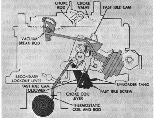
CHOKE SYSTEM WITH SECONDARY LOCKOUT FEATURE (Fig. 16)
On some models, a secondary throttle valve lock-out is used in place of the air valve lock-out feature. This type design is used on applications where little or no air flow can be tolerated from the secondary throttle bores during engine warm up. On these applications, a lock-out lever located on the float bowl is weighted so that a tang on the lower end of the lever catches a lock pin on the secondary throttle shaft and holds the secondary throttle valves closed. As the engine warms up, the choke valve opens and the fast idle cam drops. When the engine is thoroughly warm, the choke valve is wide open and the fast idle cam drops down so that the cam follower is completely off the steps of the cam. As the cam drops the last few degrees it strikes the secondary lock-out lever and pushes it away from the secondary valve lock-out pin. This allows the secondary valves to open and operate as described under the Power System.
On all 4MV models, the choke system is equipped with an unloader mechanism which is designed to partially open the choke valve, should the engine become loaded or flooded. To unload the engine, the accelerator pedal must be depressed so that the throttle valves are held wide open. A tang on a lever on the choke side of the primary throttle shaft contacts the fast idle cam and through the intermediate choke shaft forces the choke valve slightly open. This allows extra air to enter the carburetor bores and pass on into the engine manifold and cylinders to lean out the fuel mixture so that the engine will start.
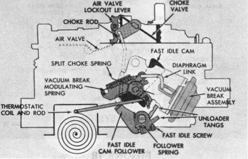
CHOKE SYSTEM (Fig. 17)
FIGURE 17
Some early model 4MV carburetors use a vacuum break modulating spring and split choke spring. The vacuum break modulating spring allows the vacuum break (choke valve position) to vary according to ambient temperature. The vacuum break modulating spring, connected to the vacuum break link, allows varying choke openings depending on the closing force of the thermostatic coil. As the closing force of the coil increases (cool weather), the link is allowed to move in the slotted lever until the modulating
FIGURE 16