9D-3
|
|
|
|
|
|
|
|
|
|
|
MODELS 2G-2GC-2GV PAGE 6
|
|
|
|
|
|
|
|
|
|
| |
|
|
|
|
|
|
|
|
|
|
|
| |
|
|
|
|
|
|
|
|
|
|
|
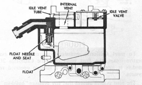
The float bowl on Vega 1-1/4" 2GV models (See Figure 3) is externally vented by a pressure relief valve through a tube mounted in the carburetor air horn. On cars shipped vertically by rail (VERT-PAK), a connecting hose is added from the pressure relief valve tube to the vapor canister to transfer any raw fuel that may be present in the float bowl to the vapor canister.
|
|
The Model "G" 2-bore carburetor has an idle system to supply the correct air/fuel mixture ratios to the engine during idle and low speed operation. The idle system is necessary during this period because air flow through the carburetor venturi is not great enough to cause fuel to flow from the main discharge nozzles. Each bore of the carburetor has a separate and independent idle system.
|
IDLE VENT VALVE (Fig. 4)
|
|
|
|
|
|
In the conventional idle system, during curb idle the throttle valves are held slightly open by the idle speed adjusting screw or, in some applications, by the idle stop solenoid. The small amount of air which passes between the throttle valves and bores is regulated by the screw or solenoid plunger to give the engine the desired idle speed.
|
| |
|
|
|
|
|
|
|
|
|
| |
 |
|
|
| |
|
|
Since the engine requires very little air for idle and low speeds, fuel is added to the air by the application of vacuum (low pressure) from the intake manifold, directly through the idle system to the fuel in the carburetor float bowl. With the idle mixture screw holes located in a high vacuum (low pressure) area below the throttle valves and the fuel in the float bowl vented to atmosphere, the idle system operates in the following manner:
|
| |
|
|
|
|
|
|
|
|
|
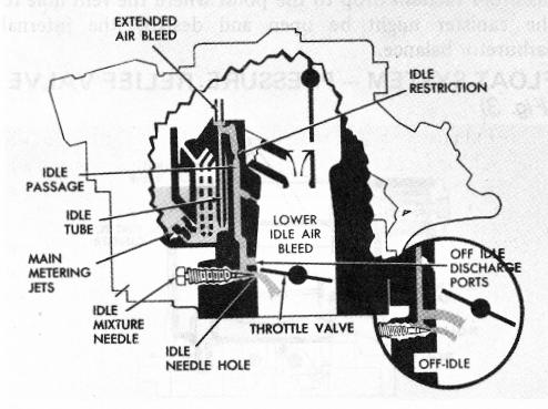
Fuel from the float bowl flows through the main metering jets into the main fuel well. It is then picked up and metered by the calibrated orifice at the tip of the idle tubes. It then passes up the idle tubes and is mixed with air from air bleeds located at the top of the idle tubes and in the idle cross channels in the venturi cluster casting. The mixture then passes downward in the idle channels through a calibrated restriction to the off-idle discharge holes or port located just above the throttle valves. Here the fuel mixture is again bled with air and then moves to the idle mixture screw holes where it is discharged and blends with the air passing the slightly open throttle valves and enters the intake manifold as a combustible mixture.
|
| |
|
|
FIGURE 4
|
|
|
|
|
| |
|
|
|
|
|
|
|
|
|
The idle vent valve on Chrysler 1-1/4" 2GV models, located at the top of the float bowl, is open during engine idle. The purpose of the external vent valve is to allow any vapors, formed during hot engine idle or hot "soak", from being forced into the carburetor bores. The vapors are vented from the float bowl through a tube which leads to the crankcase vent tube.
|
|
| |
|
|
|
|
|
|
|
|
|
IDLE SYSTEM IDLE SYSTEM (Fig. 5)
|
|
|
|
|
|
|
On some 2GV models, the top idle bleed over the idle tube has a pressed-in tube approximately 1/2-inch high which extends the bleed above the top of the venturi cluster to prevent the possibility of ice formation in these orifices during certain operating conditions. Ice formation occurs if the extended idle air bleed is not used because less heat is applied to the air horn area due to removal of the hot air choke housing. Without the extended air bleed, icing closes off the bleed, thereby causing rich idle mixtures.
|
| |
|
|
|
|
|
|
|
|
|
 |
|
|
| |
|
The idle mixture screw controls the amount of fuel mixture which enters each carburetor bore. If the idle mixture screw or needle is backed out, more mixture is admitted to the intake manifold and the engine runs rich. If the screw is turned in, the engine runs lean. In this manner, the idle mixture is varied for best idle.
|
| |
|
On exhaust emission control carburetor applications, the idle mixture screw discharge holes have been reduced in size. This was done to limit richness in the idle and off-idle ranges. Also, starting in 1971 and later, some exhaust emission control carburetors have idle mixture screw limiter caps to prevent over-adjustment in the field of the mixture
|
| |
|
|
FIGURE 5
|
|
|
|
|