| |
|
|
|
|
|
|
|
|
|
|
|
|
|
|
|
9D-3
MODELS 2G-2GC-2GV
PAGE 7
|
| |
|
|
|
|
|
|
|
|
|
|
|
|
|
|
|
|
|
|
|
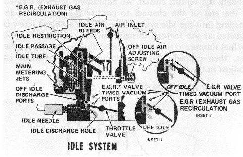
screws to upset exhaust emissions. Some idle systems have a calibrated restriction in the throttle body mixture passage to help control fuel percolation in the idle channel.
|
|
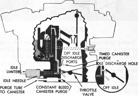
off-idle discharge ports and connect to a common tube usually located between the two idle mixture needles on the throttle body assembly. These purge ports operate during the off-idle, part throttle, and power operation of the carburetor to provide maxima n purge of the canister for complete evacuation of all fuel vapors.
|
Also, on some applications, lower idle air bleeds are used in the idle system to supplement fuel flow after off-idle operation and during the main metering system operation. During idle, they act as air bleeds. Operation of the lower idle air bleeds is explained under the main metering system section.
|
|
| |
Some 2GC, 2GV carburetors use constant bleed purge ports in addition to timed purge ports. The purge tube, located between the idle mixture screws, leads into a cavity in the throttle body casting. A small bleed hole leads from the cavity into each carburetor bore beneath the throttle valve to provide a constant purge of the canister during the engine idling period. As the throttle valves are opened beyond the idle position, additional purge of the vapor canister is provided by each of the timed purge ports.
|
OFF IDLE OPERATION (See Figure 5)
|
|
|
|
|
|
As the throttle valves are opened and more air is entering the engine to increase engine speed, additional fuel is needed to combine with the extra air. This is accomplished by the off-idle discharge holes. As the throttle valves move past the off-idle holes, they become progressively exposed to high vacuum below the throttle valves and the extra fuel needed is supplied by these holes.
|
|
| |
|
NOTE: 1970 Pontiac California 2GV carburetors do not use timed purge ports but have purge ports located in an area above the throttle valves to purge fuel vapors from the canister in the part throttle operating range.
|
|
|
The idle and off-idle holes supply sufficient fuel for engine requirements until air velocity is high enough in the venturi area to obtain fuel flow from the main metering system.
|
|
|
|
|
| |
Some 2GV applications do not include purge ports in the carburetor throttle body; purging of the vapor canister is by a hose leading to the air cleaner snorkel.
|
| |
|
|
NOTE: Some carburetors use slotted off-idle discharge ports in place of the conventional off-idle discharge holes. Either method gives the correct air/fuel mixture ratios. The type used is determined by engine requirements.
|
|
|
|
|
| |
|
|
|
|
|
|
EXHAUST GAS RECIRCULATION (E.G.R.)
|
|
|
|
| |
|
|
|
|
|
|
(Fig. 7)
|
|
|
|
|
|
|
| |
|
|
|
|
|
|
|
|
|
|
|
|
|
|
|
|
|
|
|
|
|
|
|
|
|
|
 |
|
CONSTANT AND TIMED CANISTER PURGE
|
|
|
|
|
(Fig. 6)
|
|
|
|
|
|
|
|
|
|
| |
|
|
|
|
|
|
|
|
|
|
|
|
| |
|
 |
|
|
|
| |
|
|
|
|
|
|
FIGURE 7
|
|
|
|
|
| |
|
|
|
|
|
|
|
|
|
|
|
| |
|
|
|
An Exhaust Gas Recirculation (E.G.R.) valve is used on some vehicle applications to circulate exhaust gases back into the intake manifold to lower combustion temperatures to control oxides of Nitrogen (NOx) emissions.
|
| |
|
|
|
|
|
|
|
|
|
|
|
| |
|
|
|
|
FIGURE 6
|
|
|
|
|
|
|
| |
|
|
|
|
|
|
|
|
|
|
|
Most 1971 and later G.M. passenger cars and light-duty trucks use a vapor canister to collect raw fuel vapors from the fuel tank as the tank is not vented to atmosphere.
|
|
The E.G.R. valve is operated by a vacuum signal taken from the carburetor. A vacuum supply tube, installed in the float bowl beneath the spark tube, connects by a channel to timed vacuum ports located just above the throttle valves in the throttle body bore.
|
In order to purge the canister of these raw fuel vapors, a timed canister purge system, or a combination of timed canister purge and constant canister purge, is included in the throttle body of some 2GC, 2GV carburetors. The timed purge ports (one in each bore) are located next to the
|
|
| |
As the throttle valves are opened beyond the idle position, the first E.G.R. port (See inset 1, Figure 7) is exposed to manifold vacuum to supply a signal to the
|