|
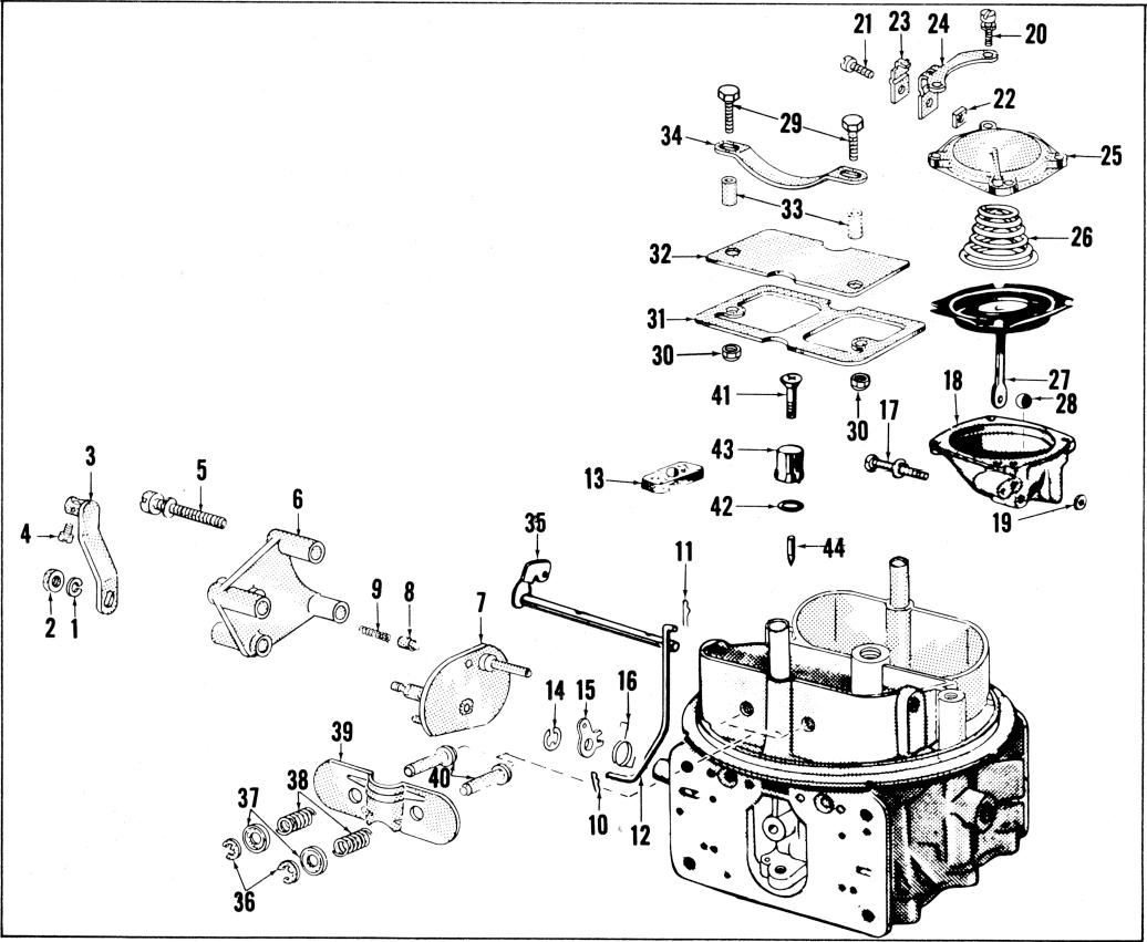
12. DISASSEMBLY PROCEDURE MODEL 4150MG |
|
Disassembly of the primary and secondary
fuel bowls for this model is the same as the 1959
model 2300 and 4150 carburetor. |
|
| |
|
|
|
|
|
The subassemblies are similiar to the 4150G
except for the differences shown in the following
exploded views. |
|
|
|
|
|
|
| |
Refer to paragraph 8 (Figure 2) and paragraph
11 (Figure 14). |
|
| |
|
|
|
|
|
|
|
|
|
 |
| |
|
|
|
|
|
|
|
|
|
| |
|
|
Figure 18. Disassembly-Main Body 4150MG |
|
|
|
| |
|
|
|
|
|
|
|
|
|
Removal |
|
|
|
Removal |
|
|
|
|
|
|
|
|
10 |
|
|
|
|
|
Choke Control |
|
|
11 |
|
Rod |
|
|
|
| |
Choke Lever and Swivel Assembly | |
|
12 |
|
Rod |
|
|
|
Choke Control |
|
|
13 |
|
Rod |
|
| |
|
|
|
14 |
|
Rod |
|
|
|
Fast Idle Cam |
|
|
|
|
|
| |
|
|
15 |
|
Rod |
Lever and BushingAssembly |
|
|
Fast Idle Cam |
|
|
16 |
|
|
|
|
Fast Idle Cam |
|
|
17 |
|
|
|
|
Fast Idle Cam |
|
|
|
|
|
|
|
|
|
18 |
Diaphragm |
|