Order of
Removal |
|
Order of
Removal |
|
|
|
|
|
| |
Diaphragm Housing Gasket (Secondary) | |
31 |
|
|
|
|
|
| |
Diaphragm Cover Assembly Screw | |
32 |
|
|
|
| |
|
33 |
|
|
|
|
|
|
34 |
|
|
|
|
|
|
35 |
|
|
|
|
|
|
36 |
|
|
|
|
|
|
37 |
| |
Valve Plate Retainer Cover | |
|
|
|
|
|
38 |
|
|
|
| |
|
39 |
|
|
|
|
|
| |
Diaphragm Spring (Secondary) | |
40 |
|
|
|
|
|
| |
Diaphragm Assembly (Secondary) | |
41 |
| |
Pump Discharge Nozzle Screw | |
|
|
|
|
| |
Diaphragm Housing Check Ball | |
42 |
Pump Discharge Nozzle Gaskets |
|
|
|
|
|
43 |
|
|
|
|
|
|
44 |
| |
Pump Discharge Needle Valve | |
|
|
| |
|
|
|
|
|
|
|
|
|
|
|
| |
 |
|
| |
|
|
|
|
|
|
|
|
|
|
|
| |
|
|
|
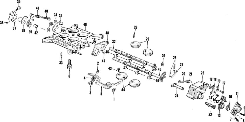
Figure 19. Disassembly-Throttle Body 4150MG |
|
|
|
| |
|
|
|
|
|
|
|
|
|
|
|
Removal |
|
|
|
|
Removal |
|
|
|
|
|
|
|
11 |
|
| |
|
|
|
|
12 |
| |
Choke Control and Pick-Up Lever | |
|
|
|
Operating Lever Adjusting Screw |
|
|
|
|
|
|
|
|
|
|
13 |
| |
Pick-Up Lever and Swivel Assembly | |
|
|
|
Operating Adjusting Screw Spring |
|
|
14 |
| |
Pick-Up Lever Bracket Assembly | |
|
|
|
|
|
|
|
|
|
|
| |
Throttle Body Screw and Lockwasher | |
|
|
15 |
|
|
|
|
|
|
16 |
|
|
|
|
|
|
|
17 |
|
|
|
|
|
|
|
18 |
|
| 10 |
|
|
|
|
19 |
|