

HYDRAULIC COMPONENT OPERATION
Functions of Valve and Hydraulic Control Units
The valves used in the Turbo Hydra-Matic 350 trans
mission can be classified into three groups:
1. Regulator Valves change pressures of the oil as it passes
through the valve. It does this by bleeding-off (or
exhausting) some of the volume of oil supplied to it.
The greater volume supplied to it, the greater is the
bleed-off. Examples of these valves are the Pressure
Regulator, Vacuum Modulator, Governor, and Detent
Pressure Regulator.
2. Control Valves direct oil through passages without
changing the pressure. Examples are the Manual Valve
and Shift Valves.
3. Timing Valves control the speed at which all passes
from one area to another, and thereby time (or smooth
out) shift changes. Examples of these are the ball and
restriction combination, restrictions alone (as in for
ward clutch passage) and accumulator pistons and
springs which act to cushion and time the oil supply
circuits.
Pressure Regulator Valve
The transmission is automatically controlled by a hydrau
lic system. Hydraulic pressure is supplied by the transmission
gear type oil pump, which is engine driven through the con
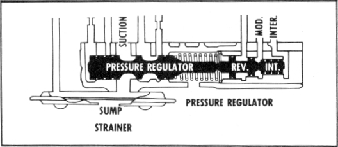
verter. Mainline pressure is controlled by a pressure regulator
(fig. 18M) valve train located in the pump housing. This
regulator controls line pressure automatically, in response to a
pressure signal from a modulator valve, in such a way that the
torque requirements of the transmission are met and smooth
shifts are obtained at all throttle openings.
To control line pressure properly, a modulator pressure is
used which varies in the same manner as torque input to the
transmission. Since the converter torque output is the product
of engine torque and converter ratio, modulator pressure must
compensate for changes in either or both of these.
To meet these requirements, modulator pressure is regu
lated by engine vacuum which is an indicator of engine torque
and carburetor opening. It is decreased by governor pressure
with an increase in vehicle speed because converter torque
ratio does the same.
Vacuum Modulator Assembly
The vacuum modulator assembly regulates line pressure
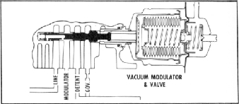
Fig. 19M-Vacuum Modulator
with modulator oil pressure that varies with torque to the
transmission. It senses forces created by:
a. The vacuum modulator bellows to increase modulator
pressure.
b. Engine vacuum acting on a diaphragm to decrease
modulator pressure.
c. Governor pressure which is generated by the governor
assembly. This pressure tends to decrease modulator
pressure.
The engine vacuum signal is provided by the vacuum
modulator (fig. 19M) which consists of an evacuated metal
bellows, a diaphragm and springs. These are so arranged that
when installed, the bellows and one spring apply a force which
acts on the modulator valve. This force acts on the modulator
valve so that it increases modulator pressure. Engine vacuum
and the other spring act in the opposite direction to decrease
modulator pressure, therefore; Low engine vacuum = high
modulator pressure and high engine vacuum = low modulator
pressure.
Governor Assembly
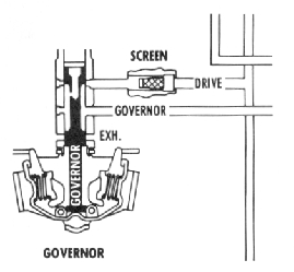
The governor assembly (fig. 20M) regulates a speed sensi
tive oil pressure that increases with output shaft or vehicle
speed. Governor pressure is used to vary the shift points and
modulator pressure.
The vehicle speed signal to the modulator valve is supplied
by the transmission governor, which is driven by the output
Fig. 18M-Pressure Regulator
f-ig. 20M-Governor
