used) in well in float bowl. Gently lower air horn assembly on gasket and locating dowels until properly seated.
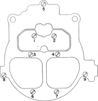
2. Install (9) air horn to float bowl attaching screws. (2) long screws go through secondary side of air horn at rear and (2) countersunk screws inside primary bores next to venturi. Install air valve lockout guard, if used, under intermediate length screw (#4 in Figure 45) and secure with self-tapping screw. If used, install air horn baffle (secondary side) beneath #3 and #4 air horn screws. Tighten all screws evenly and securely - in sequence as shown in Figure 45.
NOTE: Do not install air horn screw #5 on 4MV models using vacuum operated vent switch valve until cover is installed (See step 5).
3. Connect choke rod into lower choke lever inside bowl cavity; then install upper end of rod into upper choke lever and retain rod in upper lever with clip. On 4MC models, connect choke rod into lower choke lever inside bowl cavity; then install upper end of rod into upper choke lever by aligning squirt on rod with hole in lever and retain the upper choke lever to the end of the choke shaft with attaching screw, making sure tang on upper choke lever is beneath tang on air valve lockout lever. Tighten screw securely.
NOTE: Make sure that the flats on the end of the choke shaft align with flats in the choke lever.
4. Install idle vent valve on locating pins after engaging with actuating wire. Install attaching screw and tighten securely.
NOTE: Some later models use a thermostatically-controlled idle vent valve. On these, install the thermostatic bi-metal strip first then
9D-5
MODELS 4M-4MC-4MV
PAGE 31
NOVEMBER, 1973
REPLACES PAGES
31 and 32 in
9D-5 SERVICE MANUAL
J DATED MAY 1973
the spring arm on top of the bi-metal strip.
Then install attaching screw. Install dust cover
under air horn screw.
5. On models using a vacuum operated vent switch valve, carefully install diaphragm and stem in diaphragm retainer; then install diaphragm and retainer in air horn, making sure diaphragm is not wrinkled or torn. Lightly tap diaphragm retainer into air horn assembly until fully seated.
Install diaphragm spring over diaphragm stem and, with stem raised, compress spring while sliding vent valve assembly under slot in diaphragm stem.
NOTE: Part number and "RP" on vent valve
face upward. Install vent valve cover gasket,
cover, and screw. Align cover with holes in air
horn and tighten screw securely. Install longer
air horn screw in vent valve cover and air horn
and tighten screw securely. Install pump over
ride lever on diaphragm stem and retain with
small screw. Tighten screw securely.
6. Install (2) secondary metering rods into the secondary metering rod hanger (upper ends of rod point towards each other). Install secondary metering rod holder onto air valve cam follower. Install retaining screw and tighten securely. Work air valves up and down several times to make sure they are free in all positions.
7. Connect pump lever to upper end of pump rod. If two-hole pump lever is used, make sure pump rod is in correct hole - see specifications. Place pump lever on air horn casting. Align hole in pump lever with hole in air horn casting and push pump lever roll pin back through casting until end of pin is flush with casting.
NOTE: If the "clipless" pump design is not
used, install pump rod in pump lever and retain
with clip.
8. After the inside thermostatic coil lever is adjusted, the thermostatic coil, cover and gasket assembly should be installed and rotated counterclockwise until the choke valve just closes. At this point, the index cover should be set as specified.
NOTE: On 4MC models, the thermostatic
coil lever inside the choke housing has to be
indexed properly before installing the choke
thermostatic coil, cover, baffle, and gasket
assembly. (See Adjustment Procedures Bul
letin 9D-5A in the Delco carburetor 9X
manual.)
9. On models using a C.E.C. valve or idle stop solenoid, install attaching screw(s) securing C.E.C. or idle stop solenoid bracket to float bowl. Tighten screw(s) securely.
NOTE: If the C.E.C. valve or idle stop solenoid
was removed from the bracket, refer to steps 5
and 6, pages 20 and 21, reversing order for
installation of the solenoid to the bracket.
FIGURE 45