MODELS 4M-4MC-4MV PAGE 26
3. Remove screws securing idle stop solenoid bracket (if used) to float bowl and remove solenoid and bracket assembly.
CAUTION: The idle stop solenoid should not be immersed in any type of carburetor cleaner and should always be removed before complete overhaul.
NOTE: If solenoid replacement is necessary, bend back lockwasher retaining ears and remove retaining nut.
4. Remove fuel inlet filter nut, gasket, filter, and spring. Some models use a filter screen with no pressure relief spring. Consult the parts list for each model for proper parts application.
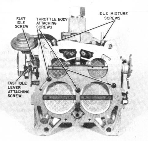
5. Invert float bowl-throttle body assembly and carefully place on clean flat surface. Remove attaching screws and remove throttle body from float bowl.
NOTE: Some early models use a center screw and lockwasher (See Figure 41) in throttle body.
6D Remove throttle body to bowl insulator gasket.
i
FIGURE 41
THROTTLE BODY DISASSEMBLY - (Figure 41)
NOTE: Place throttle body assembly on carburetor holding fixture to protect throttle valves. Extreme care must be taken to avoid damaging throttle valves.
1. Remove pump rod from throttle lever by rotating rod out of primary throttle lever.
2D DO NOT REMOVE idle mixture limiter caps, if equipped, unless it is necessary to replace the mixture needles or normal soaking and air pressure fails to clean the idle passages. If the idle mixture needles are removed, readjust the idle mixture per recommended instructions furnished by the vehicle manufacturer.
IMPORTANT: Before removing the idle mixture needle, it is suggested count the number of turns to bottom the old mixture needle. Then, when installing a new needle, lightly bottom: the new needle and then back off the number of turns it took to bottom the old needle. Proceed to adjust needles to final idle mixture following vehicle manufacturer's procedures and specifications noted in Service Manual.
3. Remove idle mixture needles and springs, if required.
4. The fast idle lever and fast idle cam follower lever can
be removed for replacement by removing attaching
screw in end of primary throttle shaft.
NOTE: Some models have a torsion spring which ties the two levers together. Make sure to check spring location for ease in reassembly.
CAUTION: No further disassembly of the throttle body is required or desirable. Under no circumstances should the plug at the front of the throttle body on certain emission control carburetors be removed to adjust the A.P.T screw behind it. The ADP.T screw is factory set for emission control and should not be readjusted in the field. A new throttle body should be installed if any damage to the existing throttle body is encountered. Service throttle bodies are available only as complete assemblies. A.P.T adjustment instructions are included in the service package.
CLEANING AND INSPECTION OF PARTS
1D Thoroughly clean carburetor castings and metal parts in an approved carburetor cleaner, such as Carbon X (X-55) or its equivalent.
CAUTION: The following should NOT be immersed in carburetor cleaner; However, the delrin (plastic) cam on the air valve shaft will withstand normal cleaning in carburetor cleaner (Rinse thoroughly after cleaning.):
a. Any rubber parts, plastic parts, diaphragms, pump
plunger.
b. Metal and plastic vacuum break assemblies.
c. Choke housing plastic tube seal (4MC models). d. Choke coil and cover assembly (4MC models).
e. Intermediate choke lever shaft cup seal recessed in
float bowl plastic insert (4MC models).
NOTE: DO NOT ATTEMPT TO REMOVE
PLASTIC INSERT.