pose is to provide good fuel distribution at lower air flows by providing, as near as possible, equal fuel distribution to all engine cylinders.
4. An air horn baffle is used on some models to prevent incoming air from the air cleaner reacting on the secondary main well bleed tubes. The baffle is located adjacent to the secondary well bleed tubes and extends above the air horn between the primary and secondary bores. This prevents incoming air from forcing fuel level down in the secondary wells through the bleed tubes and prevents secondary nozzle lag on heavy acceleration.
5. Some models use notched secondary air valves to reduce the vacuum signal at the nozzles for leaner air/fuel mixture ratios during initial air valve opening. The leaner mixtures assist in meeting emission requirements and also improve throttle response when operating at high altitudes.
AIR VALVE DASHPOTS
AIR VALVE DASHPOT OPERATION (Fig. 13)
FIGURE 13
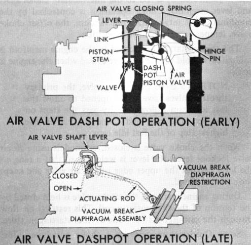
There are two different type air valve dashpots used in the Quadrajet carburetor. Their primary purpose is to control the opening rate of the air valves and prevent secondary discharge nozzle lag.
The early type dashpot (Top of picture, Figure 13) consists of a piston which operates in a fuel well adjacent to the float bowl. The piston stem is connected to the air valve through a link and lever assembly. As the air valves open, the dashpot piston is pulled upward forcing
fuel to flow between the side of the piston and fuel well which retards the air valve opening. A rubber washer attached to the piston stem acts as a check valve. During upward movement of the piston, the rubber washer seats and forces all fuel flow around the piston. When the air valve closes, the check valve unseats and allows fuel to also pass through the center of the piston allowing the air valves to return closed rapidly.
The late type air valve dashpot (Lower picture, Figure 13) operates off of the choke vacuum break diaphragm unit. The secondary air valve is connected to the choke vacuum break unit by a rod, to control the opening rate of the air valve.
Whenever manifold vacuum is above approximately 5"-6" of Mercury (Hg), the vacuum break diaphragm is seated (plunger is fully inward) against spring tension. At this point, the vacuum break rod is in the forward end of the slot in the air valve lever, or in the rear of the slot in the vacuum break plunger, and the air valves are closed.
During acceleration or heavy engine loads when the secondary throttle valves are opened, the manifold vacuum drops. The spring located in the vacuum break diaphragm overcomes the vacuum pull and forces the plunger and link outward which, in turn, allows the air valves to open. The opening rate of the air valves is controlled by the calibrated restriction in the vacuum inlet in the diaphragm cover. This gives the dashpot action required to delay air valve opening enough for efficient fuel flow from the secondary discharge nozzles.
PUMP SYSTEM
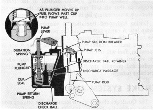
ACCELERATING PUMP SYSTEM (Fig. 14)
FIGURE 14
During quick acceleration, when the throttle is opened rapidly, the air flow and manifold vacuum change almost instantaneously. The fuel, which is heavier, tends to lag behind causing a momentary leanness. The accelerator