Some Quadrajet carburetors have a fuel pull-over enrichment system to provide added enrichment and improved fuel control during higher engine speeds and carburetor air flows (Figure 11).
Two calibrated holes, one in each primary bore, are located either just above or just below the choke valve and feed fuel from tubes that extend into the float bowl. During high carburetor air flows, low pressure created in the air horn bore pulls fuel from the high-speed fuel feeds, supplementing fuel flow from the primary main metering system. The pull-over enrichment system begins to feed fuel at approximately 8 lbs. of air per minute and continues to feed at higher engine speeds to provide extra fuel necessary for good engine performance.
On those carburetor models that have the two calibrated holes located just below the choke valve (See Choke System 4MV), the pull-over enrichment system feeds additional fuel at closed choke for good cold engine starting. Calibrated air bleeds, located in the air horn, are used with this system.
The pull-over enrichment system allows the use of slightly leaner mixtures during part throttle operation and still provide enough fuel during high-speed operation. This feature gives added refinement to the fuel mixtures for exhaust emission control.
POWER SYSTEM POWER SYSTEM (Fig. 12)
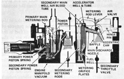
FIGURE 12
The power system in the Quadrajet carburetor provides extra mixture enrichment to meet power requirements under heavy engine loads and high-speed operation. The richer mixtures are supplied through the main metering systems in the primary and secondary sides of the carburetor (Figure 12).
The fuel mixture is enriched in the two primary bores through the power system. This consists of a vacuum operated power piston and a spring located in a cylinder
connected by a passage to intake manifold vacuum. The spring under the power piston pushes the piston upward against manifold vacuum force tending to pull the piston downward.
During part throttle and cruising ranges, manifold vacuums are sufficient to hold the power piston down against spring tension so that the larger diameter of the primary metering rod tip is held in the main metering jet orifice to provide leaner mixtures during these periods of engine operation. However, as engine load is increased to a point where extra mixture enrichment is required, the power piston spring overcomes the vacuum pull on the power piston and the tapered tip of the primary metering rods moves upward in the main metering jet orifice. The smaller diameter of the metering rod tip allows more fuel to pass through the main metering jet and enrich the fuel mixture to meet the added power requirements. As engine load decreases, the manifold vacuum rises and extra mixture enrichment is no longer needed. The higher vacuum pulls downward on the power piston against spring tension, which moves the larger diameter of the metering rod into the metering jet orifice returning the fuel mixture to normal economy ranges.
A dual power piston spring is used beneath the power piston in the piston bore of some Quadrajet models (Figure 12). The smaller diameter power piston spring seats in the center of the piston and bottoms on the float bowl casting. The spring is used to control power enrichment during light engine loads. A larger diameter spring surrounds the smaller inner spring and exerts additional pressure on the bottom of the power piston to provide efficient mixture ratios at heavier engine load conditions. The dual power piston spring feature, on models so equipped, assists in providing improved fuel control of air/fuel mixture ratios to meet emission and power requirements of the engine.
The primary side of the carburetor provides adequate air and fuel for low-speed operation. However, at higher speed, more air and fuel are needed to meet engine demands. The secondary side of the carburetor is used to provide extra air and fuel through the secondary throttle bores.
The secondary section of the Quadrajet has a separate and independent metering system. It consists of two large throttle valves connected by a shaft and linkage to the primary throttle shaft. Fuel metering is controlled by spring loaded air valves, metering orifice plates, secondary metering rods, main fuel wells with bleed tubes, fuel discharge nozzles, accelerating wells and tubes. The secondary metering system supplements fuel flow from the primary side and operates as follows:
When the engine reaches a point where the primary bores cannot meet engine air and fuel demands, a lever on the primary throttle shaft, through a connecting link to the secondary throttle shaft, begins to open the secondary throttle valves, provided the engine has warmed the choke coil to release the secondary lockout lever, if used. As the