| 9 of 40 |  |
transfer holes which act as additional
air bleeds.
(There is only one idle transfer hole
on truck car
buretors.) The fuel is discharged from
the idle
discharge hole into the strong manifold
vacuum
below the throttle plates. The idle
discharge hole
in both throttle bores is equipped
with an idle ad
justing needle which is used to control
the mixture
delivered at idle only. Turning the
needle in toward
its seat restricts the flow of fuel,
thus providing a
leaner idle mixture. Turning the needle
out en
riches the mixture by allowing a greater
flow of
fuel. Directly under the idle needles
is a groove
in the manifold mating surface of
the throttle body.
This groove allows manifold heat to
warm the area
around the idle discharge holes and
eliminates
the possibility of icing.
During off-idle operation when the
throttle
plate is moved slightly past the idle
transfer holes,
the idle transfer holes begin discharging
fuel as
they are exposed to manifold vacuum.
As the throt
tle plate is opened still wider and
engine speed
increases, the air flow through the
carburetor is
also increased. This creates a vacuum
in the
venturi strong enough to bring the
main metering
system into operation. The flow from
the idle
system tapers off as the main metering
system
begins discharging fuel. The two systems
are
engineered to provide a smooth gradual
transition
from idle to cruising speeds.
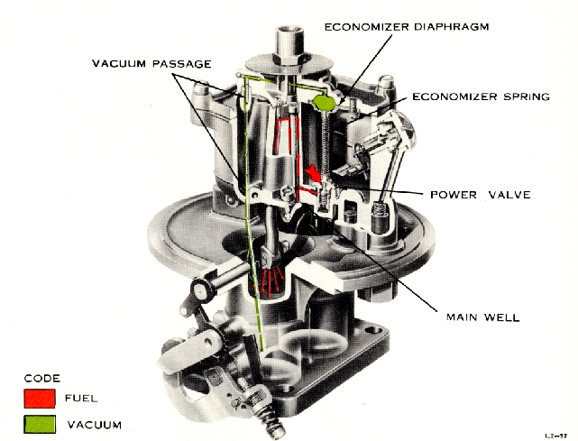
POWER ENRICHMENT SYSTEM
4. POWER ENRICHMENT SYSTEM
During high power operation, the carburetor
must deliver a richer mixture than
is needed when
the engine is running at cruising
speed with no
great power output required. The added
fuel for
efficient operation is supplied by
the power en
richment system, sometimes referred
to as the
economizer system.
The power enrichment system is controlled
by manifold vacuum, which gives an
accurate
7-