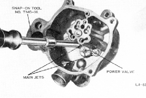
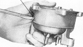
FIGURE 19. REMOVING MAIN JETS
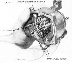
FIGURE 16. REMOVING PUMP DISCHARGE
NEEDLE,
IDLE TUBES AND MAIN WELL TUBES
8. Tilt the main body to remove the
two idle
tubes, two main well tubes, and
pump discharge
needle. Discard these parts.
11. Remove and discard the two main
jets,
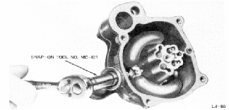
the power valve and the power valve
gasket. Use
Snap-On Tool No. TMC-36 for the
main jets and
Snap-On Tool No. MC-127 for the
power valve.
FIGURE 17. REMOVING FUEL INLET VALVE
SEAT
9. Using Snap-On Tool No. MC-125,
remove
and discard the fuel inlet needle
seat and gasket.
FLOAT SHAFT
L4-
FIGURE 18. REMOVING FLOAT SHAFT
10. Remove the float shaft and carefully
re
move the float assembly, fuel inlet
needle and
clip, and float spring. Discard
the float shaft and
the fuel inlet needle and clip.
Do not attempt to remove the hex-head
accelerating pump discharge nozzles
from
the governor equipped carburetors.
They
are pressed into position and should
not be
disturbed.
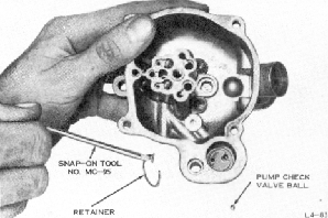
FIGURE 20. REMOVING PUMP CHECK VALVE
AND RETAINER
12. With Snap-On Tool No. MC-95,
remove
the pump check valve retainer and
tilt the main
body to remove the pump check valve
ball. Dis
card the retainer and ball.
NOTE
