| 9 of 76 |  |
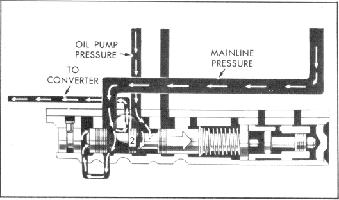
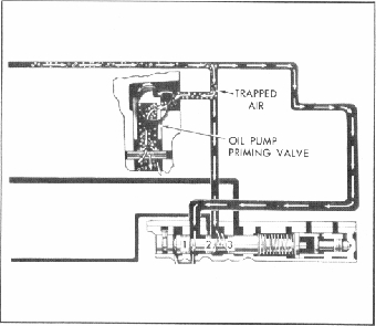
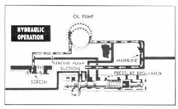
Fig. 7PG-Oil Pump Circuits
Fig. 9PG-Converter Charging Circuit
(Fig. 7PG), fluid is drawn from the sump (oil pan) through a
fine mesh screen and into the suction side of the pump. Out
put fluid under pressure enters a passage leading to the area
between spool 1 and spool 2 of the pressure regulator valve
and to the cavity at the extreme left of the pressure regulator
valve (Fig. 8PG). Pressure in this cavity causes the valve to
move to the right against spring pressure.
NOTE: Since the various spools of the pressure regulator
valve are the same size, oil pressure between the spools
alone does not cause the valve to move.
As oil pump output is being delivered, it is directed
through a passage to an area between spools 2 and 3 of the
pressure regulator valve. This same passage also delivers oil to
the oil pump priming valve (Fig. 8PG). The priming valve pro
vides an exhaust for any air that may be trapped in the system.
The priming valve spring holds the valve in an open position
allowing any trapped air to exhaust. As the hydraulic pressure
builds up in the oil pump circuit, the valve is forced into its
bore, closing the exhaust bleed hole.
Converter Charging Circuit
As soon as sufficient hydraulic pressure is developed, this
force acting on the left end of the pressure regulator valve,
moves the valve to the right against opposing spring force. This
motion causes the number 2 spool to uncover the converter
feed passage. Fluid in the area between spools 1 and 2 then fill
the converter. (Fig. 9PG). The converter is kept fully charged
in this way any time the oil pump is operating and supplying
pressure. The converter is filled through the area between the
converter hub and the stator support by a passage drilled in
the oil pump cover.
Since the converter is continually turning when the engine
is running, the oil is thrown outward and the return location is
in the area between the input shaft and the I.D. of the stator
support. This converter out oil then enters the oil cooler
passage of the oil pump. If the unit is equipped with a remote
oil cooler, the oil passes over the opening of the oil cooler
by-pass valve which is preset to open at approximately 45 psi
and is directed to the oil cooler supply line. Pressures in excess
of 45 psi unseats the by-pass valve and enters the lubrication
circuit.
Fig. 8PG-Oil Pump Priming Valve
Lubrication Circuit
Oil cooler return oil and any by-pass oil join in a passage at
the rear of the by-pass valve and is then called lubrication oil
pressure. On units not equipped with the remote oil cooler,
the converter out oil transfers through the cooler by-pass valve
passage (even though there is no cooler by-pass valve) and
enters the lubrication circuit.
Beginning at the rear end of the cooler by-pass port, the
lubrication circuit is identical on all versions of the Aluminum
Powerglide (Fig. IOPG). Lubrication oil is supplied to the
input shaft between two metal seal rings where it enters a main
oil gallery drilled from the rear of the shaft. This gallery
supplies lubrication oil to the high and reverse clutch plates,
the planetary components, and the various bushing and thrust
washer surfaces.
Mainline Pressure Circuit
As the converter and lubrication circuits are charged,
mainline pressure continues to increase, thus placing more
force on the left end of the pressure regulator valve. This
increased force moves the regulator valve further to the right