| 59 of 76 |  |
b. Partial leak in line from engine to modulator.
c.
Improper engine vacuum.
d. Vacuum operated accessory leak. (Hoses, vacuum ad
vance, etc.)
2. Damaged Modulator
a.
Stuck valve.
b. Water in modulator.
c.
Not operating properly. See vacuum
Modulator Assembly
3. Detent System
a.
Detent valve or cable stuck in detent position.
4. Pump
a.
Incorrect pressure regulator spring.
5. Valve Body
a.
Pressure regulator and/or boost yalve stuck.
Causes of Improper Vacuum at Modulator
1. Engine
a.
Tune up.
b.
Loose vacuum fittings.
c. Vacuum operated accessory leak (hoses, vacuum ad
vance, etc.).
2. Vacuum Line To Modulator
a. Leak.
b. Loose fitting.
Governor Pressure Check
The vacuum modulator has three areas to be checked. If
any one of the three areas fails to pass the prescribed checks,
the modulator must be replaced.
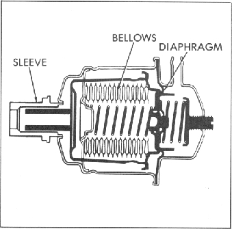
Fig. 38M-Vacuum Modulator Assembly
Vacuum Modulator Assembly
1.
Install line Pressure Gage.
2.
Disconnect vacuum line to modulator.
3.
With car on hoise (rear wheels, off ground), foot off brake,
in drive, check line pressure at 1000 RPM.
4. Slowly increase engine RPM to 3000 RPM and determine
if a line pressure drop occurs (7 PSI or more).
5.
If not pressure drop occurs:
a.
Inspect Governor
(1) Stuck valve.
(2) Weight freeness.
(3) Restricted orifice in governor valve.
b. Governor Feed System
Modulator Assembly Diagnosis Procedure
A defective vacuum modulator can cause one or more of
the following complaints.
1.
Harsh upshifts and downshifts.
2. Delayed upshifts.
3.
Soft upshifts and downshifts.
4.
Slips in low, drive and reverse.
5. Transmission overheating.
6. Engine burning transmission oil.
If any one of the above complaints are encountered, the
1.
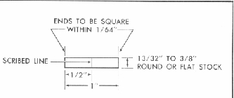
Bellows Comparison Check.
Using a comparison gage, compare the load of a known
good modulator of the same part number with the modulator
in question. Fabricate modulator comparison gage as shown
Fig. 39M-Modulator Comparison Gauge
To check bellows load, proceed as follows:
a. Insert one end of the comparison gage into the sus
pected defective modulator sleeve. Insert the opposite
end of the gage into a known good modulator the same
NOTE: The part number of the modulator assembly is
located on the back side of the modulator.