| 28 of 76 |  |
Clutches
From the foregoing, it is apparent that a planetary unit is
actually an operational transmission. All that is needed to
make it work is a way to prevent rotation of any one of the
planetary members to provide reduction or low speed and a
way to lock any two planetary members together to provide
direct drive or high speed. The units which provide such
Multiple Disc Clutch
The multiple disc clutch serves the purpose of connecting
or disconnecting two moving units to or from each other.
This clutch (fig. 6M) consists of a hub, drive plates, driven
plates, drum, piston, and release springs. The drive plates,
mounted on the hub, have internal serrations which engage
with splines on the hub. The driven plates have outer serra
tions which engage with splines in the drum. All the plates are
free to move independently.
When the apply piston has hydraulic pressure applied
against it, it forces the drive plates together. This locks the
drum and hub together (fig. 7M), and they rotate as a unit.
The clutch is released by the release springs (fig. 8M)
which push the apply piston back as soon as hydraulic pressure
on the piston is cut off. This allows the plates to separate. The
drum and hub are now disengaged, and the hub can turn free
of the drum.
Roller Clutches
A one way clutch allows (fig. 9M) rotation of a unit in
one direction and locks the unit from rotating in the opposite
direction. Two roller clutches are used in the 3-speed auto
FRICTIONAL UNITS
Fig. 10M-Band Application
matic transmission to lock one member of each planetary gear
set for reduction. In direction drive, both clutches allow free
rotation.
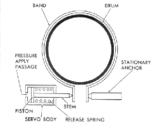
Intermediate Overrun Brake Band
An intermediate overrun brake band (fig. 10M) is used
(single wrap type) on the 3-speed transmission.
The band fits over the direct clutch drum into two slots in
the transmission case. It is activated by an intermediate servo
piston and rod assembly located in the transmission case.
This band provides engine braking when the selector lever
is in the LZ range.
MECHANICAL POWER FLOW
Figures II M through 17NI relate the mechanical power
flow of the 3-Speed Automatic transmission. Each figure gives
an explanation of what component is applied or released in
each stage of transmission operation.