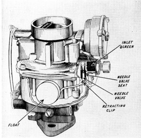
Figure 5. Float System PUMP SYSTEM
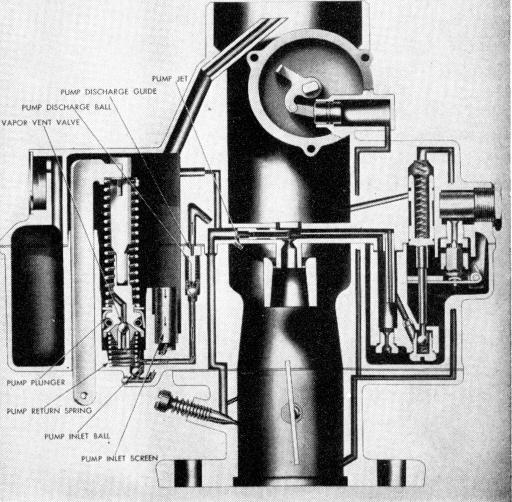
To provide fuel for smooth quick acceleration a double spring pump plunger is used in the Model "BC" Carburetor. (As shown in Figure 6.) The rate of compression of the top spring versus the bottom spring is calibrated to insure a smooth, sustained charge of fuel for acceleration.
To exclude dirt, all fuel for the pump system first passes through the pump screen in the bottom of the float bowl. It is then drawn past the ball check into the pump well on the intake stroke of the plunger. Upon acceleration the force of the pump plunger seats the ball check and forces fuel up the discharge passage. The pressure of the fuel lifts the .pump outlet ball check from its seat. The fuel is then sprayed on the edge of the venturi by the pump jet and delivered to the engine.
FLOAT SYSTEM
The Model "BC" Carburetor employs the conventional float needle and seat to control the fuel level in the float bowl. In accordance with concentric float bowl design, dual floats are used to maintain fuel level. (As shown in Figure 5) For some applications a small clip connects the float needle to the float. In this manner, the float needle is drawn from its seat by the float as the fuel level lowers, thereby permitting an ample entry of fuel into the bowl to meet increase engine demand.
This feature also serves to retract the
needle from its seat, if for any reason a gum residue might tend to cause a sticking condition.
Figure 6. Pump System