| |
|
|
|
|
|
|
|
|
|
|
|
|
|
|
9D-3
MODELS 2G-2GC-2GV
PAGE 29
|
| |
|
|
|
|
|
|
|
|
|
|
|
|
|
|
|
|
|
| |
|
|
|
|
|
|
|
|
|
|
|
|
|
|
|
|
|
| |
|
|
|
|
|
|
|
|
|
|
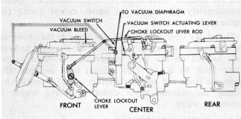
TYPICAL THREE TWO-BORE CARBURETOR INSTALLATION (Fig. 51)
|
|
| |
|
|
|
|
|
|
|
|
|
|
|
|
|
|
|
|
|
| |
|
|
|
|
|
|
|
|
|
|
 |
|
| |
|
|
 |
|
|
|
| |
|
|
|
|
|
|
|
|
|
|
|
| |
|
|
|
|
|
|
|
FIGURE 51
|
|
|
| |
|
|
|
|
|
|
|
|
|
|
|
| |
|
|
|
|
primary carburetor, contains all the conventional systems of carburetion, including float, idle, main metering, power, pump and choke. The front and rear carburetors, called the secondary carburetors, contain only float, pump and main metering systems. The primary (center) carburetor is the only one used during idle, warm-up and part throttle operation. During idle and low speeds, the two secondary (end) carburetors are kept out of operation by closing springs externally attached to the throttle shafts.
|
| |
|
|
|
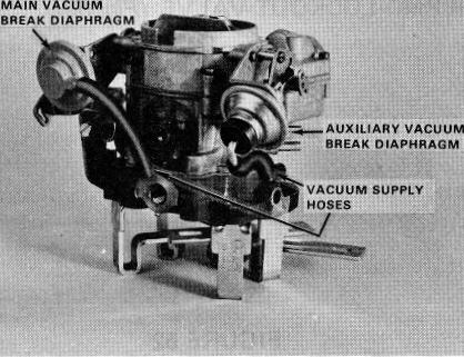
FIGURE 50
|
|
|
|
|
|
| |
|
ASSEMBLY OF 2GV WITH DUAL VACUUM BREAK - (Figure 50)
|
|
25. Install primary (main) vacuum break and bracket assembly onto throttle lever side of air horn. Rotate end of vacuum break rod so that it slides into slot in vacuum break lever on the end of the choke shaft. The other end of the vacuum break rod will slide into the vacuum diaphragm plunger lever by aligning lug on rod with slot in plunger shaft. Attach vacuum break diaphragm and bracket assembly to air horn using (2) attaching screws. Tighten securely.
|
|
| |
The throttle valves and accelerator pumps on the secondary carburetors are operated by a vacuum diaphragm which is controlled by a vacuum switch mounted on the center carburetor. The throttle shafts on the outside carburetors are connected by a common rod, so they will both operate simultaneously, controlled by the vacuum diaphragm.
|
26. Install secondary (auxiliary) vacuum break lever on end of choke shaft with retaining screw. Tighten securely.
|
|
| |
|
|
NOTE: When installed correctly, slot in lever
|
|
|
|
During idle and part throttle ranges the center carburetor feeds fuel while the outside carburetors remain out of operation. The two outside carburetors operate in the following manner: A vacuum switch located on the center carburetor is operated by a tang on the accelerator pump lever. The vacuum switch is connected directly to the engine vacuum. The switch has a vacuum line which runs to the vacuum diaphragm mounted on the front carburetor. The vacuum diaphragm is connected by linkage to the throttle lever on the front carburetor.
|
| |
|
|
hangs downward when choke valve is open.
|
|
|
|
|
27. Install secondary (auxiliary) vacuum break and bracket assembly onto air horn using (2) attaching screws, with actuating rod in slots in the vacuum break lever and vacuum diaphragm plunger - loop on secondary vacuum break rod hangs downward. Tighten vacuum break bracket attaching screws securely.
|
|
28. Install vacuum hoses to primary and secondary vacuum break assemblies. Then connect vacuum hose(s) to the fitting(s) on the throttle body.
|
|
| |
On normal acceleration only the center carburetor feeds air and fuel until the throttle valves are opened approximately 60 degrees. When the throttle valves reach this point, a tang on the pump lever of the center carburetor, opens the vacuum switch which applies vacuum to the diaphragm. Vacuum applied to this diaphragm opens the throttle valves on both front and rear carburetors simultaneously allowing air and fuel to feed from the accelerating and main metering systems.
|
|
|
|
|
|
|
|
|
|
|
|
ADJUSTMENT PROCEDURES AND SPECIFICATIONS (ALL MODELS)
|
|
|
|
Refer to the 9D-3 Section of the Delco Carburetor Parts and Service Manual for all float, pump, idle vent, vacuum break, choke, C.E.C. valve, and idle stop solenoid adjustment procedures and specifications.
|
|
THREE TWO-BORE CARBURETOR INSTALLATION
|
|
| |
On deceleration the vacuum switch closes, shutting off all vacuum applied to the diaphragm. Air is then bled from inside the front carburetor air horn by another line through the vacuum switch to the vacuum diaphragm unit, allowing
|
OPERATION (See Figure 51)
|
|
|
|
|
|
|
In this installation, three Rochester 2-bore carburetors are mounted in tandem. The center carburetor, called the
|
|