| |
|
|
|
REASSEMBLY |
|
|
|
|
|
|
| |
|
|
|
|
|
|
|
|
|
|
|
|
|
| 1. SPECIAL INSTRUCTIONS |
|
|
|
|
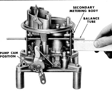
metering body to the end of the balance tube is
one inch. On models 4150G and 4150MG (trucks),
the tube is equally projected in both bowls. |
| |
|
|
|
|
|
A. PROCEDURE - The re-assembly pro
cedure is basically the reverse of disassembly,
however the following instructions will insure
good performance on the engine. |
|
| |
|
|
|
|
|
|
|
|
| |
|
 |
|
| |
|
|
|
|
|
|
|
| |
B. RE-ASSEMBLY INSTRUCTIONS BE
FORE REASSEMBLING |
|
|
|
| |
|
|
|
|
|
|
|
(1) For easier installing of the Teflon
bushings on the secondary shaft roll the Teflon
bushing between the thumb and first finger. This
helps to shape the bushing on the shaft. |
|
|
|
| |
|
|
|
|
|
|
|
(2) Always center the throttle plates in
the bore to prevent an excessive amount of air
leakage. |
|
|
|
| |
|
|
|
|
|
|
|
(3) The primary fuel bowl should be
installed before the secondary fuel bowl. |
|
|
|
| |
|
|
|
|
|
|
|
|
| |
|
|
|
|
|
|
|
|
|
|
|
|
|
| |
|
|
|
|
|
|
|
|
Figure 26. Balance Tube Adjustment |
|
|
|
(4) Lubricate all "O" ring seals to insure
easy installation and install the "O" rings on the
extreme end of the fuel line tube on four barrel
models, then they will roll on the tube when in
stalling the fuel bowl. |
|
|
|
|
|
|
|
|
|
| |
C. ADJUSTING FLOAT LEVEL - On the
bench adjustment. |
| |
|
|
|
|
|
|
|
|
| |
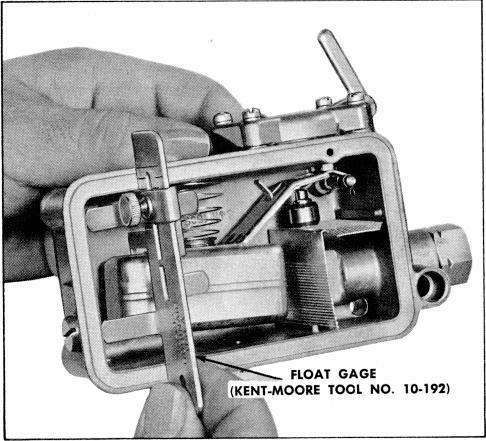
(1) On all 2300 and 4150 and 4160 models
with metal floats, the floats are adjusted with
the bowl inverted and allowing the float to drop
to a closed position. With the gauge and setting
specified on the Holley Catalog sheet for the model
carburetor, the leg of the gauge with the step
should just lightly contact the float. The float is
adjusted by bending the small tab in the float
lever with a screw driver. This applies to
primary and secondary fuel bowls. |
| |
|
|
|
|
|
(5) The throttle body to main body gasket
matches the throttle body only one way. It must
be correctly installed. |
|
| |
|
|
|
|
|
(6) On model 4160 with mechanical sec
ondarys, the idle air adjusting screw must be
installed flush with or further into the main
body so that it will not be forced against its seat
when the throttle body is installed. |
|
| |
|
|
|
|
|
|
|
|
| |
|
|
|
|
|
 |
(7) The choke plate on all models should
drop to a wide open position of its own weight
after installation, but before the choke rod is
connected. |
|
| |
|
|
|
|
|
(8) The accelerating pump diaphragm is
correctly installed with the raised boss on the
diaphragm in contact with the pump lever. |
|
| |
|
|
|
|
|
(9) Check the catalog specification sheet
for the correct pump cam position. |
|
| |
|
|
|
|
|
| 2. ADJUSTMENTS DURING ASSEMBLY |
|
|
|
| |
|
|
|
|
|
A. PROCEDURES - The following assembly
inspections and adjustments are necessary to
insure correct operation of the carburetor. |
|
| |
|
|
|
|
|
B. BALANCE TUBE - On models with a
balance tube, the distance from the secondary |
|
|
|
|
|
|
|
|
|
| |
|
|
|
|
Figure 27. Gauging Primary Float |
|
|