 |
|
|
|
|
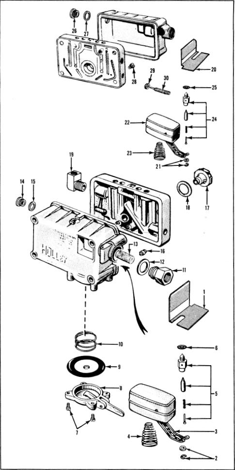
Key To Figure 14. (cont'd) |
|
|
| |
|
|
|
|
|
|
| |
Removal |
|
| |
10 |
| |
Diaphragm Assembly Spring | |
| |
11 |
|
| |
12 |
| |
Fuel Inlet Fitting Gasket | |
| |
13 |
|
| |
14 |
|
| |
15 |
|
| |
16 |
| |
Primary Metering Body Main | |
| |
|
|
| |
17 |
|
| |
18 |
|
| |
19 |
| |
Spark Fitting - If Included | |
| |
20 |
| |
Secondary Fuel Bowl Baffle Plate | |
| |
21 |
| |
Float and Hinge "E"Retainer & Washer | |
| |
22 |
|
| |
23 |
|
| |
24 |
| |
Fuel Valve and Seat Assembly | |
| |
25 |
| |
Fuel Valve and Seat Assembly Gasket | |
| |
26 |
|
| |
27 |
|
| |
28 |
| |
Secondary Metering Body Main Jets (2) | |
| |
29 |
| |
Idle Adjusting Screws (2) | |
| |
30 |
| |
Idle Adjusting Screw Seals (2) | |
| |
|
|
|
|
|
|
| |
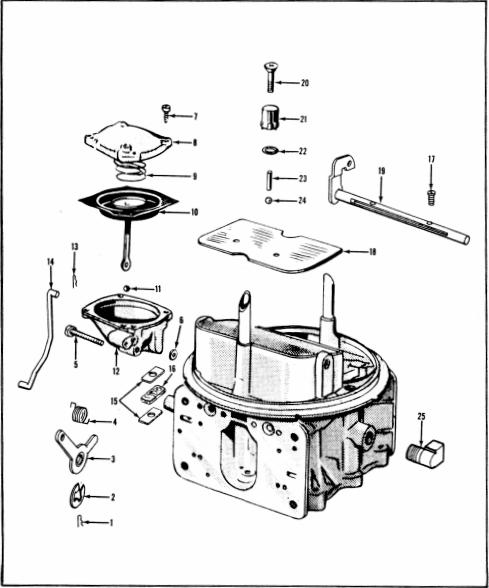
Disassembly of Primary Fuel Bowl on all
late production models is the same. Refer to
paragraph 8 (Figure 2). |
| |
|
|
|
|
|
|
| |
 |
| |
|
|
|
| |
Figure 14. Disassembly-Fuel Bowls and Metering Bodies
4150G (Early Production) |
|
| |
|
|
|
|
|
|
| 1 |
| |
Primary Fuel Bowl Baffle Plate | |
|
| 2 |
Float and Hinge "E"Retainer & Washer |
|
| 3 |
|
|
| 4 |
|
|
| 5 |
| |
Fuel Valve and Seat Assembly | |
|
| 6 |
| |
Fuel Valve and Seat Assembly Gasket | |
|
| 7 |
| |
Pump Diaphragm Cover Screws & | |
|
| |
|
|
| |
|
|
|
|
|
|
| 8 |
|
|
|
Figure 15. Disassembly-Main Body 4150G
(Early Production) |
|
| 9 |
|
|
|
|
| |
|
|
|
|
|
|