
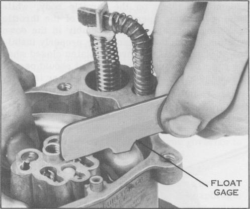
Figure 37. Gauging Float
11. Install the two idle tubes in position in the main body.
12. Slide the main well tubes into the main body. In some cases the Master Repair Kit contains two sets of main well tubes. On early models of this carburetor the head of the main well tube was smaller than that used on later models. These tubes are not interchangeable and the new set matching the head size of the original tubes must be used. The main well tube heads should be flush with or slightly below the surface of the main body casting. They must not project above the surface of the casting.
13. Place anew bowl cover gasket on the main body, then place the bowl cover plate over the gasket and the second gasket over the cover plate. Be sure all holes in the gaskets and bowl cover plate are lined up with the corresponding holes in the casting.
C. Reassembly - Airhorn Assembly
1. Assemble the bowl vent tube with the two screws.
2. Assemble the new choke housing gasket and choke housing to the air horn with the three choke housing screws, (if integral choke model).
3. Install the choke shaft, lever and piston assembly in the airhorn with the piston fitted into the piston chamber in the choke housing. Slide choke plate into the slot in the choke shaft and secure it with two new choke plate screws but do not tighten. Check the choke plate for freedom of travel to the full open and closed position. Check
to see that the edge of the choke plate fits flush with the wall of the air inlet. Tighten the choke plates and stake them tightly, with any approved staking tool.
NOTE
In some cases the choke lever and piston assembly is separate and is secured to the choke shaft by a nut and lockwasher.
4. On the models so equipped, assemble the choke lever assembly to the choke shaft.
5. Using Snap-On Tool No. MC-119A, install the economizer piston and stem assembly. If the enconomizer has the pressed in type economizer see Service Bulletin 141 for instructions on how to convert to threaded type.
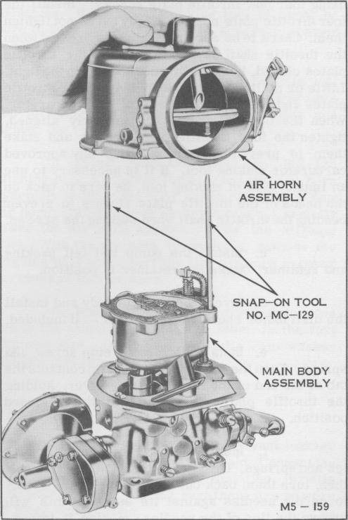
Figure 38. Installing Air Horn
6. Place anew airhorn to throttle body gasket in position, aligned with the screw holes. Carefully place the air horn in position on the main body with the aid of Snap-On Aligning Tool No. MC-129. Install the five airhorn cover screws and lockwashers.
-21