
5. Install a new power valve gasket, and the power valve using Snap-On Tool No. MC-127.
6. Place the straight end of the float spring in the small hole in the float lever. Hole the straight portion of the float in place with the forefinger and lower the float and spring into the fuel bowl so that the spring fits over the boss in the bottom of the bowl. Secure the float by installing the float shaft.
NOTE
on the float gauge should just touch the tip of the float. Check both floats. Check to see that the hinge or float does not bend on the main body casting. By working the float with the lever at the extreme ends of its lateral play on the shaft, it is possible to determine whether there is enough clearance between the lever and the float bowl to allow the float to travel through its entire range without interference. Should the bowl interfere with the lever action, a simple way to correct this condition is:
On some earlier models no float spring was incorporated. It is recommended that at this time the new type float assembly be installed on those models. The part number of the proper float may be found in the Parts Catalog Sheets.
7. Assemble the accelerating pump piston, the pump spring, washer, the pump rod, and pump rod spring. Install the pump in the main body being careful not to curl the piston on the edge of the pump chamber. Assemble the pump rod stud to the throttle lever with the pump link and retainer. (Re-install pump rod retainer ring if originally equipped). Install the pump link placing the short pin in the center hole for normal weather operation, and in the inner hole for very warm weather or in the outer hole for very cold weather.
NOTE
In some cases it will be noticed that the new replacement pump link is longer than the original pump link. The longer pump link increases the capacity of the accelerating system.
8. Grasp the fuel inlet needle valve and clip, firmly with a pair of needle nose pliers and place the inlet needle in the valve hole from the inside of the bowl and fit the clip over the float tab. Install the fuel inlet seat and gasket using Snap-On Tool No. MC-125.
NOTE
Some earlier models were not equipped with the inlet needle valve and clip assembly. The new inlet needle and clip assembly, supplied in the Master Repair Kit, will fit these older models.
9. Check the float level with the proper float gauge. With the floats raised fully, the tab
(1) With a fine tooth file, remove some of the metal from the back of the float lever. This area should be evenly rounded as a flat spot might cause sticking at the edges.
(2) Test by replacing the float and shaft float in bowl. Move float lever to one end of shaft and raise and lower float, checking clearance between the lever and the bowl.
(3) Remove any burrs that may be found on inside edges of float shaft hole.
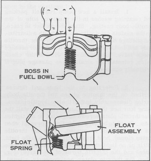
Figure 36. Installing Float Assembly
10. Install the pump discharge needle (point down). If a new needle is to be installed use the following procedure. Place a brass rod on top of the needle and tap gently a few times with a fiber mallet. Be sure the needle is free in its chamber after this operation is completed.
- 20 -