of their removal. During disassembly discard all gaskets, also all parts which have a replacement in the Master Repair Kit.
|
,s r
°
0`
a`o. oa~s' PART NAME | ||
|
28 |
1 |
Governor Line Fittings (2) |
|
29 |
2 |
Governor Cover Safety Wire and Seal |
|
29 |
3 |
Governor Cover Screw and Lock |
|
washer (4) | ||
|
29 |
4 |
Governor Cover |
|
28 |
5 |
Governor Cover Gasket |
|
28 |
6 |
Governor Spring |
|
30 |
7 |
Diaphragm Rod Cotter Pin |
|
30 |
8 |
Governor Lever Nut and Lockwasher |
|
30 |
9 |
Governor Lever |
|
28 |
10 |
Diaphragm Cover Safety Wire and Seal |
|
28 |
11 |
Diaphragm Cover Screws and |
|
Lockwashers (8) | ||
|
28 |
12 |
Diaphragm Cover |
|
28 |
13 |
Diaphragm and Rod Assembly |
|
21 |
14 |
Governor Housing Screws (2) |
|
32 |
15 |
Governor Housing |
|
32 |
16 |
Governor Housing Gasket |
|
28 |
17 |
Governor By-Pass Jet "A" |
|
28 |
18 |
Governor By-Pass Jet "B" |
|
32 |
19 |
Throttle Shaft Seal |
|
32 |
20 |
Throttle Shaft Seal Retainer |
|
32 |
21 |
Throttle Shaft Seal Retainer Spring |
|
28 |
22 |
Throttle Lever Pin |
|
28 |
23 |
Throttle Lever Clamp Screw |
|
28 |
24 |
Throttle Lever |
|
33 |
25 |
Throttle Operation Shaft Housing |
|
Screws (2) | ||
|
33 |
26 |
Throttle Operating Shaft Housing |
|
28 |
27 |
Throttle Operating Shaft Assembly |
|
28 |
28 |
Throttle Operating Housing Gasket |
|
28 |
29 |
Throttle Stop Screw |
|
28 |
30 |
Throttle Stop Screw Spring |
|
28 |
31 |
Idle Adjusting Needles (2) |
|
28 |
32 |
Idle Adjusting Needle Spring (2) |
|
34 |
33 |
Distributor Check Valve Retainer |
|
28 |
34 |
Distributor Check Valve |
|
28 |
35 |
Pump Rod Felt Packing Retainer |
|
28 |
36 |
Pump Rod Felt Packing |
|
28 |
37 |
Throttle Shaft Retainer Spring |
|
28 |
38 |
Throttle Plate Screws (4) |
|
28 |
39 |
Throttle Plates (2) |
|
28 |
40 |
Throttle Shaft |
|
28 |
41 |
Throttle Body Bearing |
and wire.
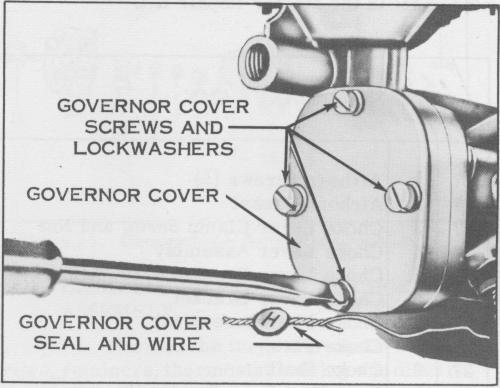
Figure 29. Removing Governor Cover Screws
c. Remove the four governor cover screws and lockwashers and remove the governor cover and gasket. Discard the gasket.
d. With the fingers, carefully, lift the governor spring off its position.
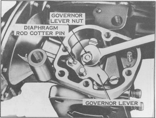
Figure 30. Removing Governor Lever Nut
e. Remove the diaphragm rod cotter pin, governor lever nut and lockwasher also the governor lever.
f. Remove the diaphragm cover seal
and wire.
b. Remove the governor cover seal
f ittings.
1. DISASSEMBLY OF GOVERNOR
a. Remove the two governor line
g. Remove the eight diaphragm cover screws and lockwasher and remove the diaphragm cover. Slide the diaphragm and rod assembly out of the housing.
-16